High-performance rectifier diode replaced circuit

A technology of rectifier diodes and alternative circuits, applied in electrical components, conversion equipment without intermediate conversion to AC, conversion of AC power input to DC power output, etc., can solve the problem of reducing power utilization efficiency, high forward voltage drop, and high energy consumption. and other problems, to achieve good application prospects, low forward voltage drop, and low self-power loss.

Active Publication Date: 2015-01-28
CHONGQING SOUTHWEST INTEGRATED CIRCUIT DESIGN
View PDF6 Cites 2 Cited by
  • Summary
  • Abstract
  • Description
  • Claims
  • Application Information

AI Technical Summary

Problems solved by technology

However, the forward voltage drop of the prior art SBR is relatively high, the forward voltage drop of the current technology is about 420mV, and the reverse leakage current of the device is 50uA, so both forward and reverse work will result in higher energy consumption , reducing the power utilization efficiency

Method used


Image

  • High-performance rectifier diode replaced circuit
  • High-performance rectifier diode replaced circuit
  • High-performance rectifier diode replaced circuit

Examples


Embodiment Construction

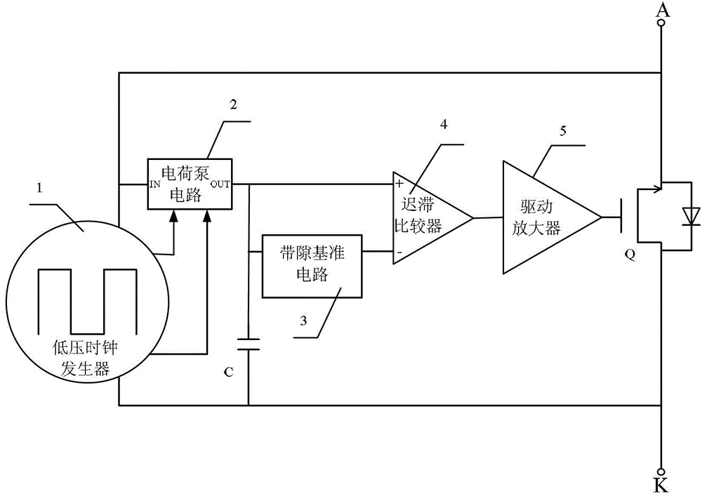
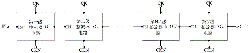
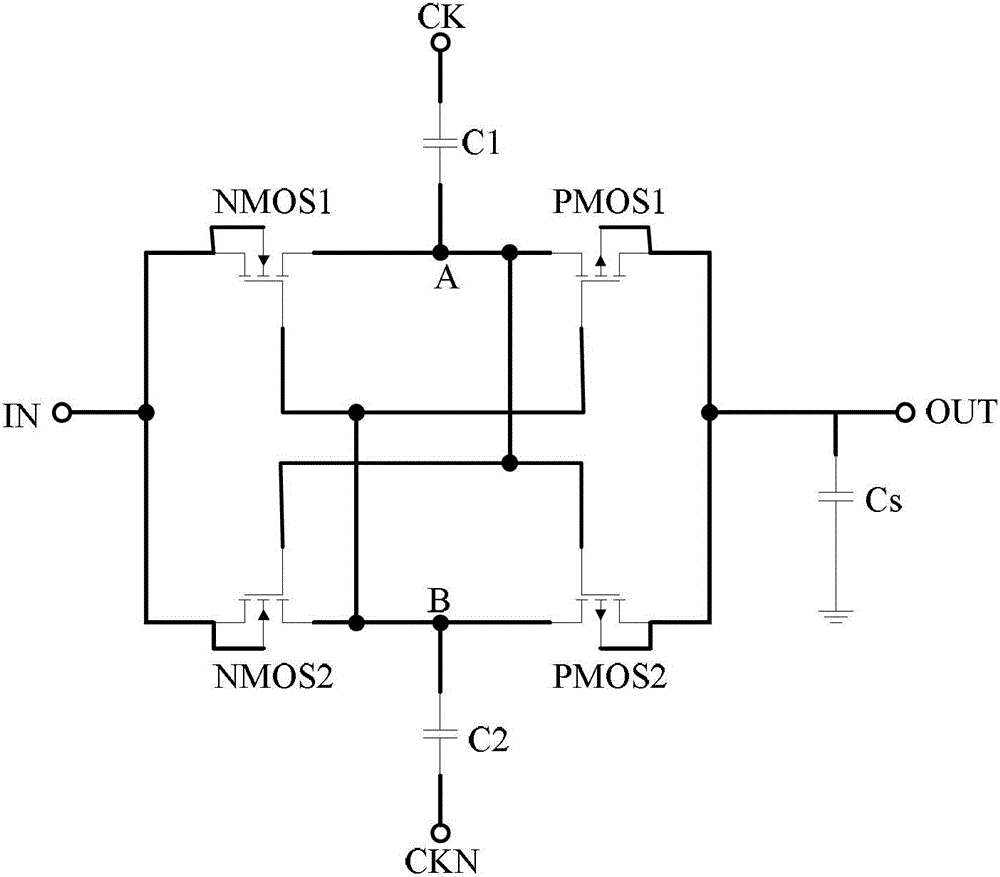
[0018] see figure 1 , figure 2 , a rectifier diode replacement circuit, including a capacitor C, a low-voltage clock generator 1, a charge pump circuit 2, a bandgap reference circuit 3, a hysteresis comparator 4, a drive amplifier 5 and a power MOS tube Q, wherein:

[0019] The low-voltage clock generator 1 detects the voltage between the drain and the source of the power MOS transistor Q, and generates a clock signal to drive the charge pump circuit 2;

[0020] The charge pump circuit 2 detects the voltage between the drain and the source of the power MOS transistor Q and stores the charge in the capacitor C after amplifying it;

[0021] The voltage stored on the capacitor C and the reference voltage output by the bandgap reference circuit 3 are respectively output to the hysteresis comparator 4 for comparison; when the voltage stored on the capacitor C is greater than the reference voltage output by the bandgap reference circuit 3, the hysteresis comparator 4 outputs Turn...


PUM


Abstract

The invention discloses a high-performance rectifier diode replaced circuit which comprises a capacitor, a low-voltage clock generator, a charge pump circuit, a band-gap reference circuit, a hysteresis comparator, a driving amplifier and a power metal oxide semiconductor (MOS) pipe and is characterized in that the low-voltage clock generator detects voltages at two ends of a diode pipe and generates clock signals to drive the charge pump circuit; the charge pump circuit detects the voltages at two ends of the diode pipe and stores the charges in the capacitor after the charges are amplified; the voltage stored on the capacitor and the standard voltage output by the band-gap reference circuit are respectively output to the hysteresis comparator for comparison; and when the voltage stored in the capacitor is larger than the standard voltage output by the band-gap reference circuit, the hysteresis comparator outputs starting signals which are amplified by the driving amplifier and then output to the power MOS pipe to drive the power MOS pipe to be conducted. The high-performance rectifier diode replaced circuit can achieve equivalent diode working characteristics through a pulse working mode and can totally replace original selective beacon radar (SBR) devices in performance and dimension.

Description

technical field [0001] The invention relates to a rectifier diode, in particular to a high-performance rectifier diode replacement circuit. Background technique [0002] With the continuous improvement of power supply efficiency requirements in power electronic systems, especially in high-current power supplies, as a widely used core device in power rectification circuits - rectifier diodes have been rapidly developed in recent years. The goal of technological development is to continuously reduce the power loss of diodes during work. The performance of diodes is improved through changes in device materials and technological progress, from ordinary diode rectifiers initially used to Schottky secondary diodes Tube rectifiers, and the latest generation of rectifiers - super barrier rectifiers (Super Barrier Rectifier, SBR), make the energy consumption of the diode lower and lower, so that more energy can be converted into useful work. [0003] The existing technical solution ...

Claims


Application Information

Patent Timeline
Patent Type & Authority Patents(China)
IPC IPC(8): H02M1/08H02M3/07H02M7/217
Inventor 张真荣李明剑刘永光吴炎辉范麟万天才徐骅
Owner CHONGQING SOUTHWEST INTEGRATED CIRCUIT DESIGN
Why Eureka
Try Eureka