Vortex generators for generating vortices upstream of a cascade of compressor blades

A technology of compressors and vanes, applied in the field of compressors, can solve problems such as the inability to fully satisfy the loss reduction of the rectifier area, and achieve the effect of increasing the stability range and improving efficiency

Active Publication Date: 2013-01-30
SN DETUDE & DE CONSTR DE MOTEURS DAVIATION S N E C M A
View PDF4 Cites 5 Cited by
  • Summary
  • Abstract
  • Description
  • Claims
  • Application Information

AI Technical Summary

Problems solved by technology

This usual solution therefore does not fully meet the need for loss reduction in the rectifier region

Method used


Image

  • Vortex generators for generating vortices upstream of a cascade of compressor blades
  • Vortex generators for generating vortices upstream of a cascade of compressor blades
  • Vortex generators for generating vortices upstream of a cascade of compressor blades

Examples


Embodiment Construction

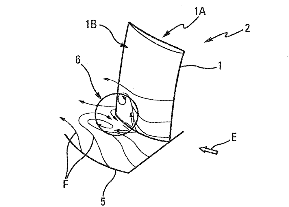
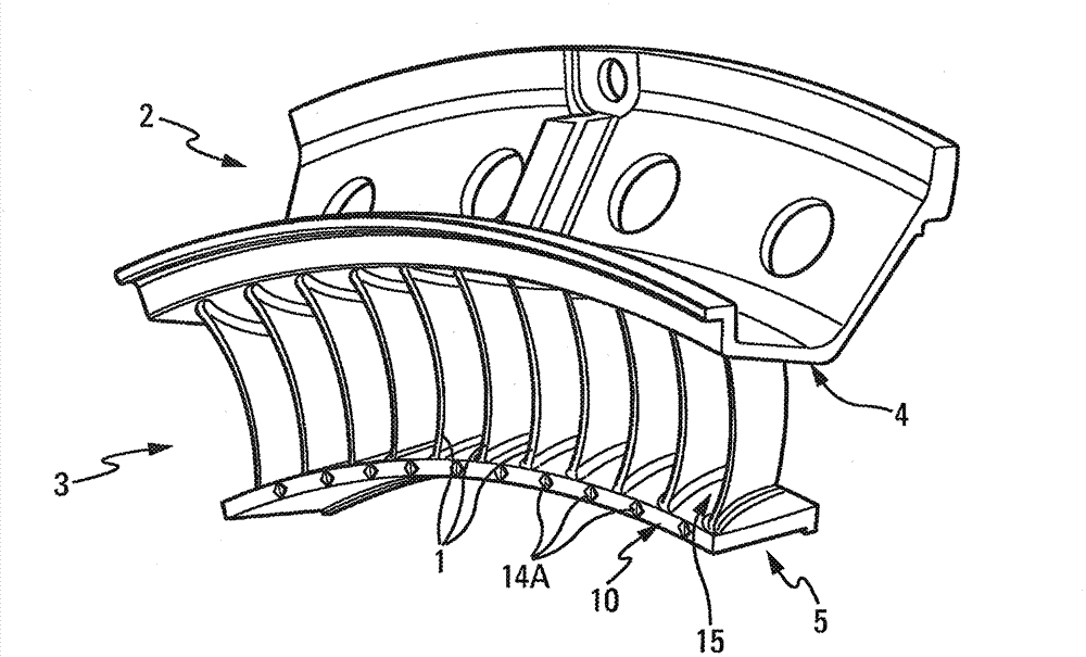
[0038] vane 1 of rectifier 2, as shown in part in image 3 and 5 as in , shown in figure 1 middle. Said rectifier 2 forms part of a compressor 3 of a turbomachine, in particular of an aircraft turbojet engine. The compressor 3 comprises, in the usual manner, a plurality of successive compression stages, each comprising a rotor 22 and a rectifier 2 (stator).

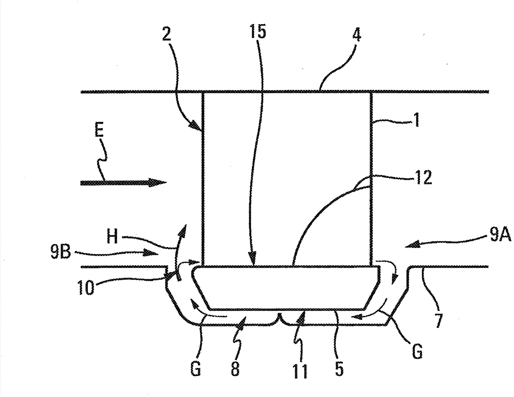
[0039] Said rectifier 2 comprises a (radial) outer shroud 4 and a (radial) inner shroud 5 , which are support shrouds for the blades 1 . Said two shrouds 4 and 5 are concentric, a plurality of vanes 1 extending substantially radially from one of said shrouds 4 and 5 to which they are fixed to the other, said blades 1 being circumferentially spaced, preferably spaced in an even manner.

[0040] Within the scope of the present invention:

[0041] - the concepts "upstream" and "downstream" are defined with respect to the direction of the main flow of air in the rectifier 2 and compressor 3; and

[0042] - The term "ra...


PUM


Abstract

The present invention relates to a bladed (1) assembly (2), particularly a flow straightener, for a turbomachine compressor, said bladed (1) assembly (2) comprising a plurality of individual devices (14A) that have an action on the flow, which are formed in such a way as at least to generate vortices (16). It is characterized in that each of said individual devices (14A) is provided upstream of said bladed (1) assembly (2) so as to act simultaneously on the main flow (E) and on a recirculating flow (G).

Description

technical field [0001] The invention relates to the field of blade assemblies for compressors of turbomachines, such as turbojet engines or turboshaft engines of helicopters. The invention also relates to a compressor comprising such a blade assembly, in particular comprising a rectifier for a high-pressure compressor. Background technique [0002] It is well known that the compression system (in particular the high-pressure compressor) for a turbojet engine is one of the most critical components of the engine. The compressor of a turbojet engine consists of a number of successive compression stages, each stage comprising two vane assemblies called a rotor and a rectifier (stator). This rectifier consists, in use, of coaxial inner and outer shrouds, and between said inner and outer shrouds vanes arranged adjacent to each other, said blades passing their ends to it, for example document FR-2896019 as disclosed. [0003] To ensure the operation of the compressor, there are ...

Claims


Application Information

Patent Timeline
Patent Type & Authority Applications(China)
IPC IPC(8): F04D29/68F01D5/14F04D29/32F04D29/52F04D29/54
CPCF04D29/321F04D29/681F04D29/541F01D5/143F01D11/001F04D29/542F04D29/544F04D29/684F05D2240/80Y02T50/60
Inventor 奥利维尔·斯特凡·多默克文森特·保罗·加布里埃尔·佩罗特阿格尼丝·帕斯蒂尔
Owner SN DETUDE & DE CONSTR DE MOTEURS DAVIATION S N E C M A
Why Eureka
Try Eureka