
Press for the direct extrusion of metallic material

Active Publication Date: 2020-06-25
DANIELI & C OFF MEC SPA
View PDF0 Cites 0 Cited by
  • Summary
  • Abstract
  • Description
  • Claims
  • Application Information

AI Technical Summary

Benefits of technology

The present invention is aimed at providing a press for the extrusion of metal materials that overcomes the drawbacks of traditional presses. The main technical effects of the invention include reduced impact on machine downtime for die replacement operations, simplified manual adjustment of the die-holder drawer, lower maintenance costs, and precise and reliable position adjustment. These effects are achieved by avoiding the sliding of the drawer on supporting elements and providing appropriate elements to support the drawer during its movement in a transverse direction. The invention ensures the integrity of supporting surfaces and reduces the frequency of maintenance operations.

Problems solved by technology

As a result of frequent die changes, the guides are subject to wear and therefore it is necessary, at regular intervals, to increase the shims under the bronze guides to ensure the correct vertical position of the die, i.e. to ensure the height centering with the extrusion axis.
This operation is rather delicate and must necessarily be performed by specialized personnel, through the use of very accurate measuring instruments.
All this results in rather prolonged machine downtimes and therefore in low productivity of the machine.
It is apparent that these additional operations also have a major impact on machine downtime and therefore on the operating costs of the machine.

Method used


Image

  • Press for the direct extrusion of metallic material
  • Press for the direct extrusion of metallic material
  • Press for the direct extrusion of metallic material

Examples


Embodiment Construction

[0033]With reference to FIGS. 4 to 7, the present invention relates to a press (generically indicated by reference numeral 1) for the extrusion of metallic material, particularly but not exclusively for the extrusion, of aluminum. The press 1 comprises a supporting structure 10, which defines an extrusion direction 500 along which the metal material is extruded through a die 2. According to a principle known in itself, the die 2 confers the shape of the section of the metal profile generated by the extrusion.

[0034]The supporting structure 10 has a configuration known in itself comprising a first crosspiece 13, near which an extrusion die 2 is placed (hereinafter also referred to as “die 2”), and a second crosspiece 14 in a position distanced from said die 2. The two is crosspieces 13, 14 are connected by columns 18 which develop in parallel defining the extrusion direction 500. With particular reference to FIG. 4, the press 1 comprises a thrust cylinder 200, integral to the, second ...


PUM

PropertyMeasurementUnit
Metallic bondaaaaaaaaaa
Displacementaaaaaaaaaa

Abstract

The present invention relates to a press for the direct extrusion of metallic material, wherein the press comprises a supporting structure which defines an extrusion axis and a transverse direction orthogonal to said extrusion axis. The press further comprises an extrusion die and a die-holder drawer, in which said die is placed. Moving means are provided for moving said drawer along a transverse direction between a first position (P1), in which said die is aligned with said extrusion axis, and a second position in which, when reached, said die can be replaced. The press according to the invention further comprises a fixed supporting element which supports the drawer at least when it occupies the first position. The press further comprises at least a movable supporting element for supporting said drawer during the movement along said transverse direction; lifting means are provided for vertically lifting the movable supporting element between a first vertical position, in which the drawer is supported by the fixed supporting element, and a second vertical position, in which the drawer is lifted with respect to the fixed supporting element and supported by said at least one movable supporting element.

Description

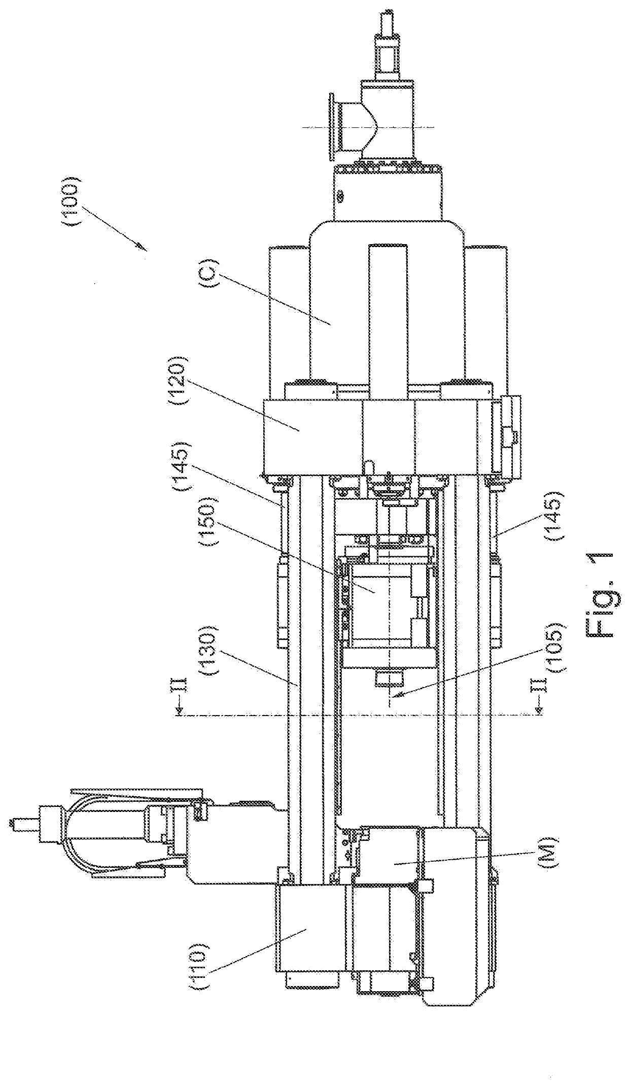
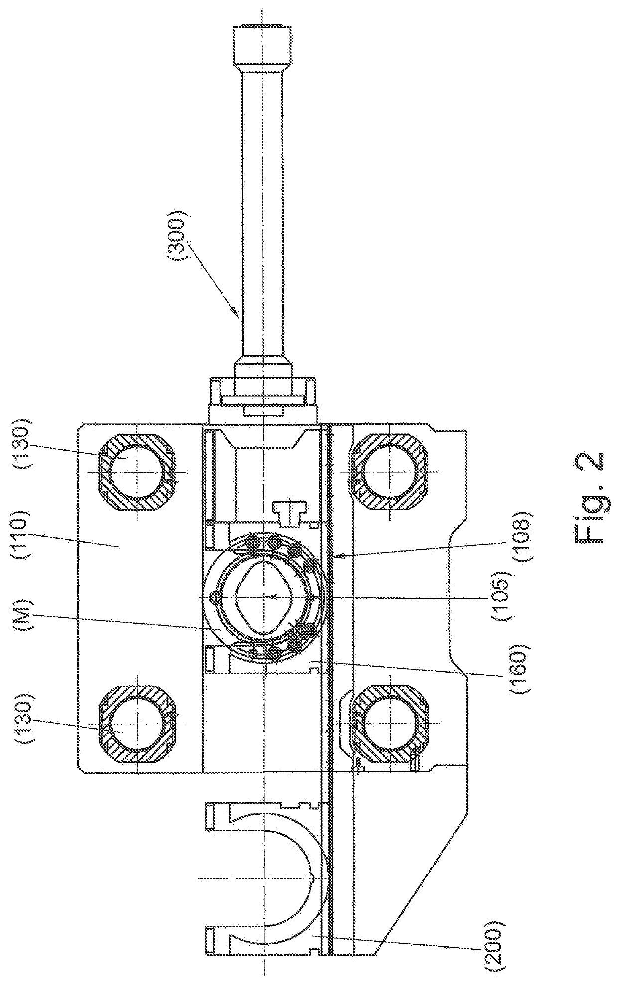
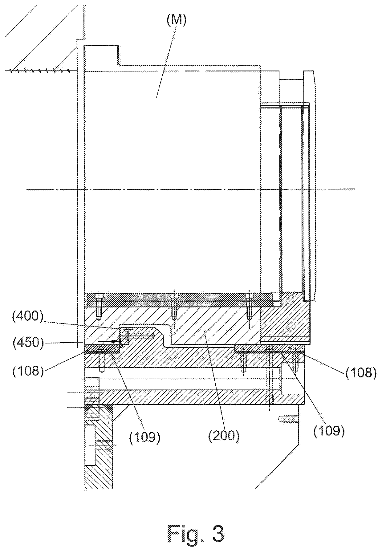
FIELD OF THE INVENTION[0001]The present invention relates to the manufacturing of items made of metallic material, either ferrous or non-ferrous, which may be aluminum section bars, for instance. In particular, the invention relates to a press for the direct extrusion of metallic material.BACKGROUND ART[0002]The use of an extrusion press is known for making metallic material section bars. In this regard, FIG. 1 shows an extrusion press (100) of known type which comprises a supporting structure defined by two crosspieces (110, 120), a front one and a rear one, connected by means of columns (130), typically four in number. A die (M) is positioned at the front crosspiece (110), which confers the shape to the section bar to be extruded.[0003]The material to be extruded is pushed through the die (M) by means of a thrust cylinder (C) integrated into the rear crosspiece, in a position substantially opposite to the die. The rear crosspiece (120) is typically anchored to the ground, while th...

Claims


Application Information

Patent Timeline
IPC IPC(8): B21C23/04
CPCB21C23/04B21C23/214B21C23/215
Inventor GALLI, ALESSANDRO MARIOMERLINI, MATTIACALVETTI, GIACOMO
Owner DANIELI & C OFF MEC SPA
Learn More