Oil mist separator

An oil mist separator and oil mist technology, applied in separation methods, dispersed particle separation, chemical instruments and methods, etc., can solve the problems of high filtration cost, small dirt holding capacity, large filtration pores, etc., and achieve long service life, The effect of simple shape structure and high precision processing

Active Publication Date: 2013-02-06
江苏威肯净化科技股份有限公司
View PDF7 Cites 9 Cited by
  • Summary
  • Abstract
  • Description
  • Claims
  • Application Information

AI Technical Summary

Problems solved by technology

The manufacturing process characteristics and single-layer structure of this filter element make the oil mist can only be filtered but not coalesced and separated, and the filter pores are large, the filtering effect is not thorough, and it is impossible to remove PM2.5 tiny oil mist particles. Single-layer structure, limited surface area in direct contact with oil fume, low dirt holding capacity, easy to clog even if the filter element is loaded with a large number, frequent replacement is required, and the filtration cost is high

Method used


Image

  • Oil mist separator
  • Oil mist separator
  • Oil mist separator

Examples


Embodiment Construction

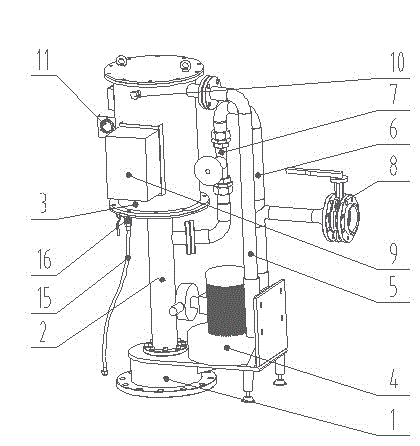
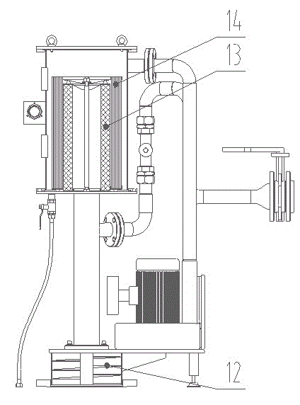
[0021] The present invention will be described in detail below in conjunction with the accompanying drawings.

[0022] In order to make the object, technical solution and advantages of the present invention clearer, the present invention will be further described in detail below in conjunction with the accompanying drawings and embodiments. The specific embodiments described here are only used to explain the present invention, not to limit the present invention.

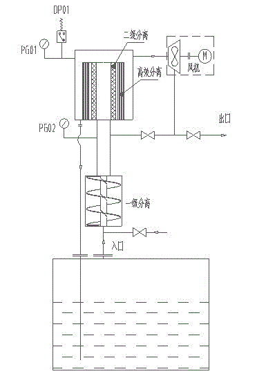
[0023] The oil mist separator of the present invention adopts a three-stage structure. The first stage adopts the high-speed rotating centrifuge method to conduct preliminary separation of large-particle oil mist; the second stage adopts the motion impact separation method to separate and gather small and medium-sized oil mist; the third-stage high-efficiency coalescing filter adopts multi-layer and multi-material composite application , change the structure of the pores multiple times, and efficiently gather and se...


PUM

PropertyMeasurementUnit
thicknessaaaaaaaaaa
thicknessaaaaaaaaaa
pore sizeaaaaaaaaaa

Abstract

The invention discloses an oil mist separator which comprises a centrifugal separation section, a spiral separation blade, a filter cylinder, a blower, a pipeline, an electric cabinet and a filter element. The oil mist separator is characterized by adopting a three-section structure including a first grade, a second grade and a third grade, wherein the first grade is used for preliminary separation of large oil mist particles according to a high speed revolution centrifuging method; the second grade is used for separating and collecting small oil mist particles according to a movement impact separation process; the third grade is used for collecting and separating residual oil blobs according to the multilayer, multi-material, composite, pore-changeable and repeated-conversion structure of an efficient coalescence-separation filter; and the efficient coalescence-separation filter adopts a three-layer structure including a filtering layer, a coalescence layer and a separating layer. According to the invention, the oil mist separator has the advantages that the outline shape is simple; various types of oil mist of different viscosities can be treated efficiently and highly accurately; and the service life is longer.

Description

technical field [0001] The invention relates to an oil mist separator configured in a lubricating system, a large gearbox, and a special workshop or space for removing oil mist. Background technique [0002] Metallurgy, petrochemical, machinery and other industries that use a large number of large, heavy-duty, high-speed equipment generally use circulating centralized oil supply devices to provide lubrication for gearboxes, bearings, and sliding shoe devices, relying on lubricating oil to bring heat generated during equipment operation back to the oil tank . This heat repeatedly heats the lubricating oil to form an oil mist, which also contains carbonized microscopic particles. The generation of oil mist and oil fume not only forms a slight positive pressure in the fuel tank, hindering the oil return process of the system, but also seriously pollutes the environment due to random discharge, increases the loss of oil products, greatly increases the concentration of particles...

Claims


Application Information

Patent Timeline
Patent Type & Authority Applications(China)
IPC IPC(8): B01D50/00
Inventor 费晓明顾志培
Owner 江苏威肯净化科技股份有限公司
Why Eureka
Try Eureka