Shell lateral punching mold

A shell side, punching technology, applied in the direction of piercing tools, manufacturing tools, metal processing equipment, etc., can solve the problems of large burrs in parts holes, increased mold maintenance costs, damage to dies or punches, etc., to reduce waste products Produce, prolong service life and reduce cost

Inactive Publication Date: 2013-02-06
DALIAN GAOHONG PRECISION MOLD
View PDF0 Cites 2 Cited by
  • Summary
  • Abstract
  • Description
  • Claims
  • Application Information

AI Technical Summary

Problems solved by technology

[0002] For the shells of many products, side punching is often required during production, such as compressor shells for refrigerators and freezers, floor parts for household air conditioners, etc., which require side punching dies, but side punching dies are not like straight punching dies The punching waste can be smoothly discharged, especially when punching thicker materials such as compressor shells, if the operator cannot clean up the waste in time to discharge the waste in time, the die and the punch will form a rigid collision , leading to damage to the die or punch with weak strength, so that the production cannot be carried out smoothly, and the punched parts have large burrs, which affects product quality and production efficiency, and the mold maintenance cost is also greatly increased.
In the waste material discharge structure of the side punching hole in the prior art, when the pieces of waste material punched out stick to each other, the waste material is easy to push against the side wall of the discharge hole and cannot be removed in time, and the die and the punching punch Rigid collision will be formed, resulting in damage to the weaker die or punch, and large burrs in the punched parts

Method used


Image

  • Shell lateral punching mold
  • Shell lateral punching mold
  • Shell lateral punching mold

Examples


Embodiment Construction

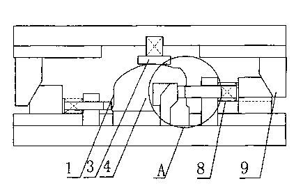
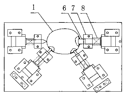
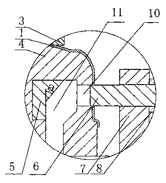
[0011] The structure of side punching die of the present invention is as Figure 1-Figure 3 As shown, the shell side punching die includes an upper die and a lower die, wherein the upper die mainly includes a clamping plate 3, an inclined die 9, and the lower die mainly includes a die 4, a slope-guided forced return structure 5, and a punch 6 , punch guide block 7, punch return spring 8; the die 4 is facing the punch 6 with a die hole 10, the outlet of the die hole 10 is connected to the vertically downward discharge hole 11, and the discharge hole 11 The position facing the punch is inlaid with a slope-guided forced return structure 5 with a slope, the angle between the slope and the vertical direction is a, and the angle a adopts the shape of the die 4 of 30°~60° and the shell 1 When punching, the casing 1 is set on the die 4, and the pressure plate 3 is pressed on the casing 1; the front end of the punch 6 is provided with a punch guide block 7 for the guidance of the punch...


PUM


Abstract

A shell lateral punching mold is characterized in that a female mold is provided with a female mold hole which is right opposite to a punch, an outlet of the female mold hole is connected with a vertically-downward discharging hole, the position of the discharging hole, which is right opposite to the punch, is provided with an oblique surface guide forcedly-returning structural member with an oblique surface, the punch and the female mold are installed on a lower mold, the lower mold is also provided with a punch guide block which is installed in the middle part of the punch, and a pressure plate is used for pressing an oblique surface of a shell skew mold which is sleeved on the female mold to be contacted with an oblique surface on the tail part of the punch. The shell side punching mold adopts an oblique surface guide forcedly returning way, the forwarding direction of punched waste is forcedly changed from the horizontal direction to the vertically downward direction under the effect of the oblique surface guide forcedly-returning structural member while the punching action is completed, so that the waste is successfully dropped one by one, the problem that the hole is blocked by the waste can be solved, success in production is guaranteed, the generation of rejects can be reduced, the production efficiency is improved, the service life of the mold is prolonged, the product quality is improved, and a purpose for reducing the cost is realized.

Description

technical field [0001] The invention relates to the technical field of molds, in particular to a shell side punching mold. Background technique [0002] For the shells of many products, side punching is often required during production, such as compressor shells for refrigerators and freezers, floor parts for household air conditioners, etc., which require side punching dies, but side punching dies are not like straight punching dies The punching waste can be smoothly discharged, especially when punching thicker materials such as compressor shells, if the operator cannot clean up the waste in time to discharge the waste in time, the die and the punch will form a rigid collision , leading to damage to the die or punch with weak strength, so that the production cannot be carried out smoothly, and the punched parts have large burrs, which affects product quality and production efficiency, and the mold maintenance cost is also greatly increased. In the waste material discharge ...

Claims


Application Information

Patent Timeline
Patent Type & Authority Applications(China)
IPC IPC(8): B21D28/34
Inventor 车向前
Owner DALIAN GAOHONG PRECISION MOLD
Why Eureka
Try Eureka