
Fixture and method for winding rectangular-section wire torsional springs

A rectangular cross-section and torsion spring technology, which is applied in the field of winding rectangular cross-section steel wire torsion springs, can solve the problems of different diameters, large differences in outer diameters, and torques that cannot meet the design requirements, so as to ensure the appearance quality and appearance. The effect of uniform diameter and uniform arrangement

Inactive Publication Date: 2014-11-05
CHONGQING WANGJIANG IND
View PDF6 Cites 0 Cited by
  • Summary
  • Abstract
  • Description
  • Claims
  • Application Information

AI Technical Summary

Problems solved by technology

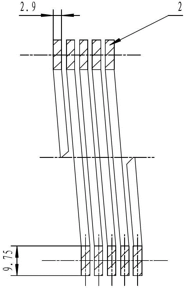
However, when torsion springs are wound with rectangular steel wires, when the dimension along the diameter of the torsion spring along the section of the steel wire is more than three times greater than the dimension along the height direction of the torsion spring (see figure 1 ), the torsion springs made by winding are prone to skewing and lodging, and it is impossible to guarantee the uniform arrangement of the torsion springs and the uniform pitch
The consequence is that the appearance quality of the torsion spring is poor, the diameter is different, the pitch difference is large, lodging and skewing occur, and the outer diameter of the torsion spring changes greatly when the torsion spring is working, which seriously interferes with other adjacent working mechanisms; the torque cannot be reached. Meet the design requirements, and the disadvantages such as large torque dispersion

Method used


Image

  • Fixture and method for winding rectangular-section wire torsional springs
  • Fixture and method for winding rectangular-section wire torsional springs
  • Fixture and method for winding rectangular-section wire torsional springs

Examples


Embodiment Construction

[0022] The present invention will be further described below in conjunction with the accompanying drawings.

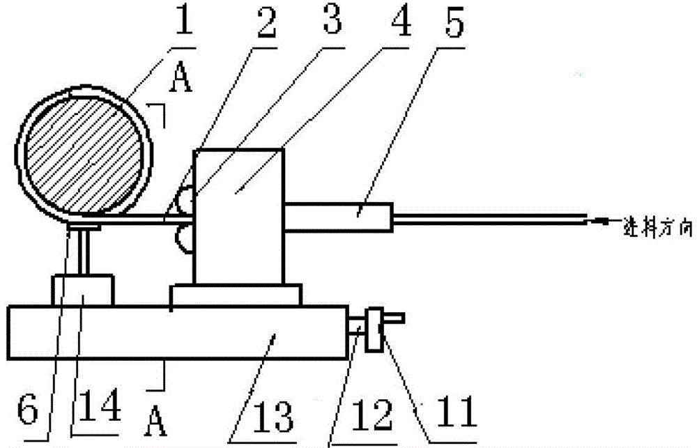
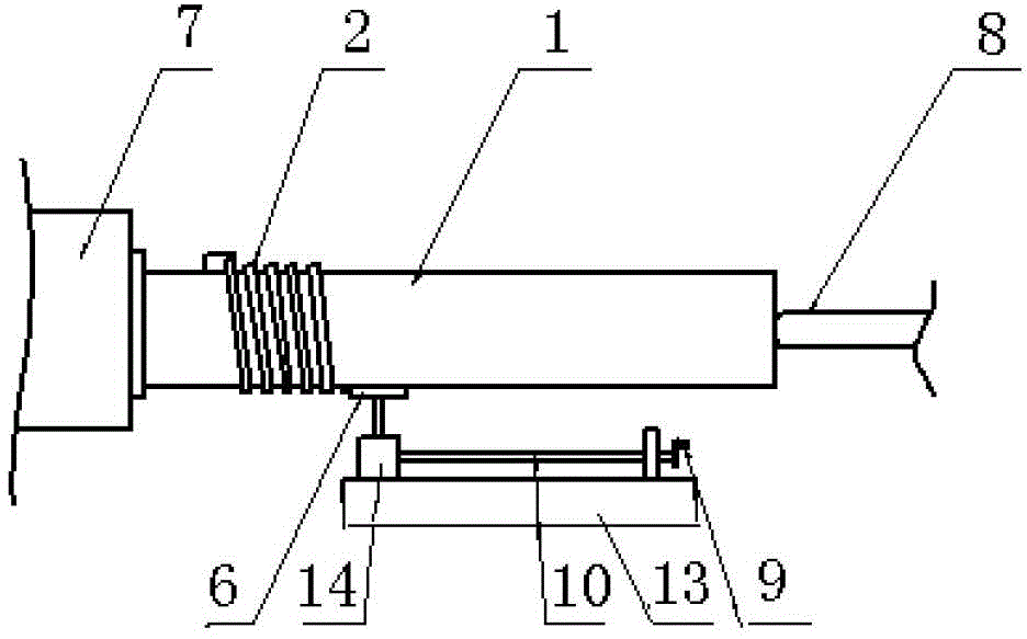
[0023] see figure 1 , figure 2 , image 3 , Figure 4 and Figure 5 , in order to ensure the consistency and reliability of the shape of the torsion spring wound with a rectangular cross-section steel wire, and to avoid the occurrence of skewing and lodging of the torsion spring during winding, the present invention provides a clamp for winding a rectangular cross-section steel wire torsion spring, Including the base plate 13 and the guide bracket 4 arranged thereon, the guide bracket 4 is connected with the base plate 13 through the first screw rod 12, and a bracket moving handle 11 is connected with one end of the first screw rod 12, Rotating the bracket moving handle can make the bracket move left and right on the base plate. It is characterized in that: the right side of the guide bracket 4 is provided with a correction splint 5, and the left side of the guide...


PUM


Abstract

The invention relates to a fixture for winding rectangular-section wire torsional springs. The fixture comprises a bed plate and a guide support arranged above the bed plate. The guide support is connected with the bed plate in a matched manner by a first screw rod, a support moving handle is connected with one end of the first screw rod in a matched manner, and the support can move from left to right on the bed plate by turning the support moving handle. A correction clamp plate is arranged on the right side of the guide support, a groove type guide wheel is arranged on the left side of the guide support, and a wire with a rectangular section sequentially penetrates through the correction clamp plate and the groove type guide wheel to be wound on a torsion mandrel. The invention further provides a method for winding the rectangular-section wire tensional springs. By the aid of the method, appearance quality of the torsional springs can be guaranteed, sizes of outer diameters of the torsional springs are consistent, and pitches are uniform. By the aid of the fixture and the method, accuracy of guiding can be guaranteed, deflection of feeding is effectively prevented, distance between a feeding outlet and the torsion mandrel can be adjusted, consistency and reliability of winding torsional spring forming are guaranteed, deflection and lodging of the torsional springs can be further avoided during winding.

Description

technical field [0001] The invention relates to a spring winding method, in particular to a method for winding a steel wire torsion spring with a rectangular section. Background technique [0002] Generally, the steel wire winding torsion spring with a rectangular cross section is carried out by setting a feeding aid on a lathe, and the feeding aid is a guide roller. However, when torsion springs are wound with rectangular steel wires, when the dimension along the diameter of the torsion spring along the section of the steel wire is more than three times greater than the dimension along the height direction of the torsion spring (see figure 1 ), the torsion springs made by winding are prone to skewing and lodging, and it is impossible to guarantee the uniform arrangement and uniform pitch of the torsion springs. The consequence is that the appearance quality of the torsion spring is poor, the diameter is different, the pitch difference is large, lodging and skewing occur,...

Claims


Application Information

Patent Timeline
Patent Type & Authority Patents(China)
IPC IPC(8): B21F23/00B21F3/00
Inventor 孙源力邢雪芳张俊华胡国发李祥坤
Owner CHONGQING WANGJIANG IND
Learn More