Lateral feeding machining cutter

A cutting tool and feeding technology, which is applied in the direction of manufacturing tools, metal processing equipment, and cutting tools for lathes, etc., can solve the problem of boring the side of the annular groove on the step surface of the workpiece step hole, and the boring of the step hole of the workpiece Cutting, increasing the cost and other issues, to achieve the effect of improving the scope of application, improving the service life and wide application range

Active Publication Date: 2015-05-20
杭州联德精密机械股份有限公司
View PDF6 Cites 0 Cited by
  • Summary
  • Abstract
  • Description
  • Claims
  • Application Information

AI Technical Summary

Problems solved by technology

[0004] The first purpose of the present invention is to overcome the problem that the existing conventional CNC machining center cannot bore the side of the annular groove on the stepped surface of the workpiece stepped hole, and provide a side feed machining tool that can effectively solve the conventional The problem that the side of the annular groove on the step surface of the workpiece step hole cannot be bored on the CNC machining center
[0005] The second purpose of the present invention is to overcome the fact that the boring tool of the existing tool with lateral feed function is a special tool. In the actual production process, too many boring tools will greatly increase the production cost; In the process of boring the side of the annular groove, the tool bar of the boring tool is easy to break. A side feed processing tool is provided. The boring tool has a wide range of applications and can be applied to many different boring surfaces. processing; and it can effectively improve the problem that the tool bar of the boring tool is easy to break during the boring process of the side of the annular groove, and improve the service life of the boring tool

Method used


Image

  • Lateral feeding machining cutter
  • Lateral feeding machining cutter
  • Lateral feeding machining cutter

Examples


Embodiment 1

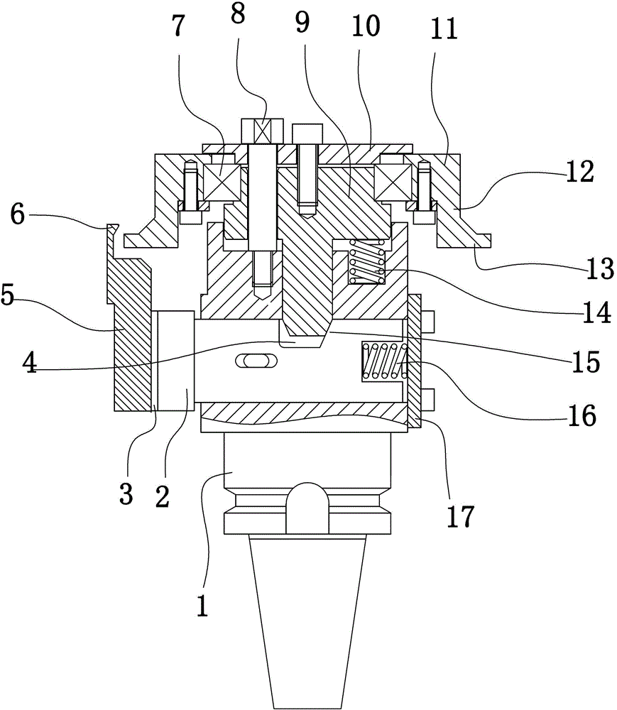
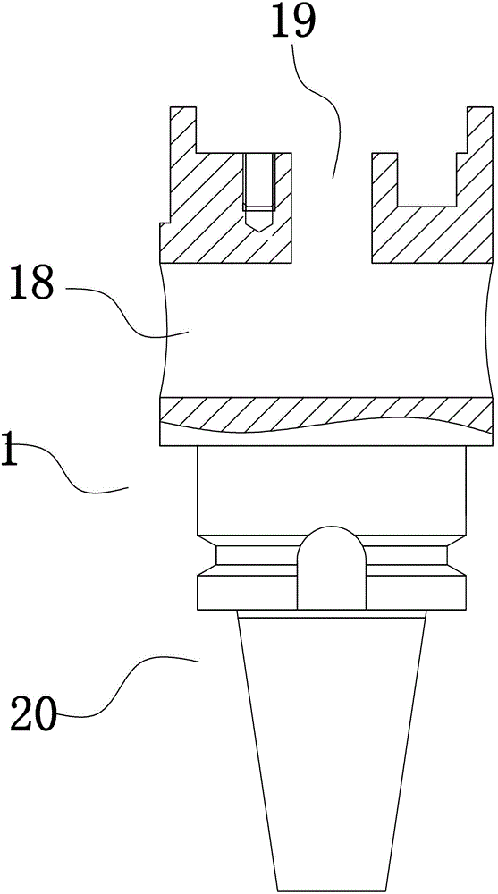
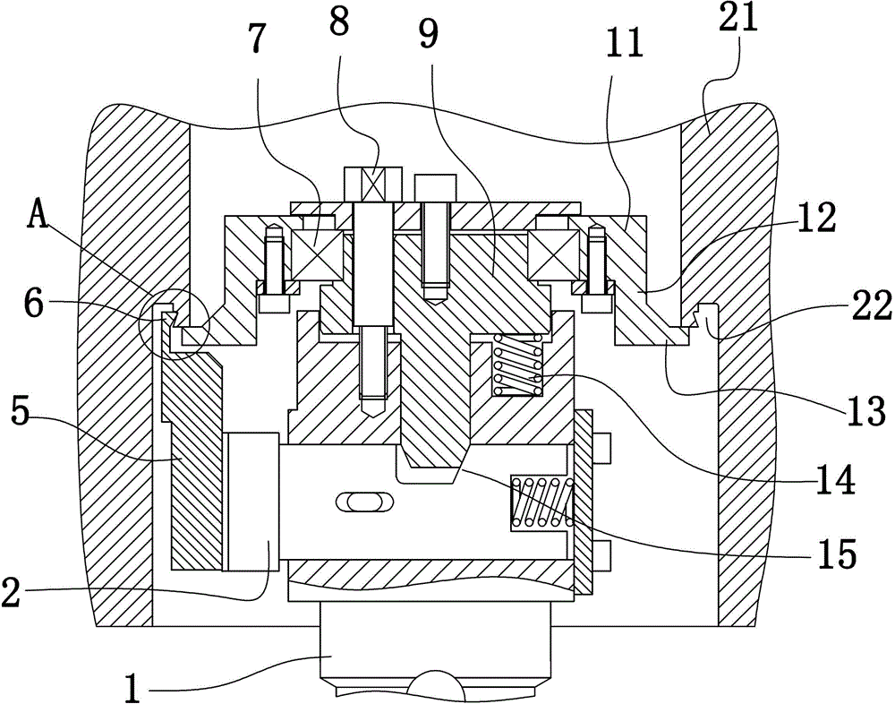
[0036] Embodiment 1: as figure 1 , figure 2 As shown, a lateral feed machining tool includes a main shaft 1, and one end of the main shaft is provided with a shank 20 connected with a cutter head of a numerical control machining center. A radial hole 18 is provided on the side of the main shaft 1 . An axial hole 19 communicating with the radial hole is provided on the end surface of the main shaft 1 opposite to the shank. The radial hole 18 is a through hole, and one end of the radial hole is provided with a blind cover 17, and the blind cover and the main shaft are connected by bolts. A slider 2 is arranged in the radial hole 18, and the cross-sections of the radial hole and the slider are circular. A keyway is provided on the side of the slider 2, a guide groove extending axially along the radial hole is provided on the side of the radial hole relative to the keyway, and a limiting block is arranged between the guide groove and the keyway. A first return spring 16 is p...

Embodiment 2

[0045] Embodiment 2: as Figure 7 , Figure 8 As shown, a side feed machining tool includes a main shaft 1, a radial hole 18 is provided on the side of the main shaft, and an axial hole 19 communicating with the radial hole is provided on the end surface of the main shaft. A slider 2 is arranged in the radial hole. A first groove 4 opposite to the axial hole is provided on the side of the slider, and a side of the first groove near the bottom of the radial hole is an inclined guide surface 15 . The inclined guide surface 15 is an arc surface, and the arc surface gradually approaches the middle of the first groove 4 from the opening end of the first groove 4 to the bottom. A mandrel 9 is slidably provided in the axial hole. A rounded corner is provided on the edge of the end surface of the mandrel near the first groove, and the arc surface of the rounded corner abuts against the arc surface of the first groove. Refer to Embodiment 1 for the rest of the structure of this emb...

Embodiment 3

[0047] Embodiment 3: A ring-shaped support sleeve is provided on the edge of the bearing seat 11 , and the ring-shaped support sleeve extends toward the slider 2 . The end of the annular support sleeve is provided with an outwardly protruding support block. The three supporting feet in Embodiment 1 are replaced by an annular supporting sleeve. Refer to Embodiment 1 for the rest of the structure of this embodiment.


PUM


Abstract

The invention discloses a lateral feeding machining cutter, and aims to provide the lateral feeding machining cutter which can effectively solve the problem that the conventional numeric control machining center cannot bore the side of an annular groove on a stage surface of a workpiece stage hole and is wide in application range. The lateral feeding machining cutter comprises a main shaft, wherein a radial hole is formed on the side of the main shaft; an axial hole communicated with the radial hole is formed on the end surface of the main shaft; a sliding block is arranged in the radial hole; a first groove opposite to the axial hole is formed on the side of the sliding block; one side, close to the bottom of the radial hole, of the first groove is an inclined guiding surface; a first reset spring is arranged between the bottom of the hole and the sliding block in the radial hole; a mandril is arranged in the axial hole in a sliding mode; one end of the mandril is extended into the first groove and presses against the inclined surface; the other end of the mandril is positioned outside the axial hole; a bearing coaxial to the main shaft is sleeved on the end of the main shaft; and a bearing seat is sleeved on the bearing.

Description

technical field [0001] The invention relates to a machining tool, in particular to a side feed machining tool. Background technique [0002] During the machining process, due to the large mass of the workpiece, it is inconvenient to locate on the ordinary lathe, so the annular groove on the side wall of the hole of this type of workpiece cannot be processed on the ordinary lathe; especially if Figure 5 As shown, the hole of the workpiece is a stepped hole and there is an annular groove 22 on the stepped surface of the stepped hole. When it is necessary to carry out boring processing on the side wall of the annular groove 22, not only ordinary lathes cannot process it, but also conventional CNC machining centers also cannot be processed. For example, yes Figure 5 Carry out boring on the side wall of the annular groove 22 in, the annular groove 22 is processed into Image 6 The dovetail groove 23 in the middle; this processing process cannot be processed on a conventional C...

Claims


Application Information

Patent Timeline
Patent Type & Authority Patents(China)
IPC IPC(8): B23B27/00B23B29/03
Inventor 孙袁
Owner 杭州联德精密机械股份有限公司
Why Eureka
Try Eureka