Stirring friction repair welding process and stirring friction welding method adopting same

A technology of friction stir and welding methods, which is applied in welding equipment, welding/welding/cutting items, applications, etc., and can solve the problems of reduced structural strength of metal shells, many processes, and long time consumption

Inactive Publication Date: 2013-02-06
FU TAI HUA IND SHENZHEN +1
View PDF5 Cites 8 Cited by
  • Summary
  • Abstract
  • Description
  • Claims
  • Application Information

AI Technical Summary

Problems solved by technology

The commonly used repair welding process is fusion welding, that is, using welding rods to melt and solidify the metal in the contact defect area together, but this fusion welding repair welding process will lead to a decrease in the structural strength of the metal shell
In order to increase the structural strength of the metal shell after repair welding, friction stir welding tools with self-consumable stirring pins are commonly used for repair welding. However, this repair welding tool needs to install a stirring pin every time welding, so the manufacturing cost is relatively high. , and the stirring needle needs to reciprocate several times in the welding defect area to stir it evenly, which requires many procedures and takes a long time

Method used


Image

  • Stirring friction repair welding process and stirring friction welding method adopting same
  • Stirring friction repair welding process and stirring friction welding method adopting same
  • Stirring friction repair welding process and stirring friction welding method adopting same

Examples


Embodiment Construction

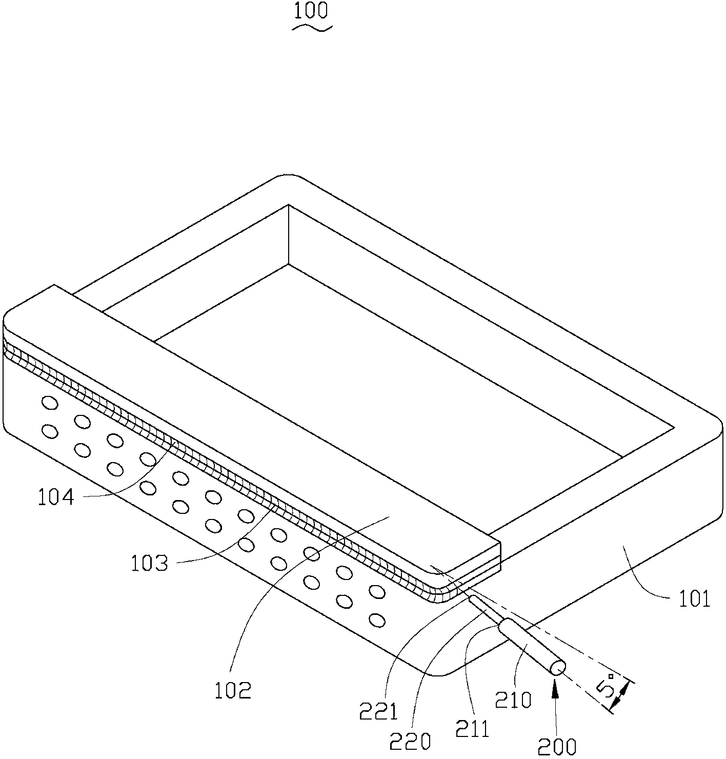
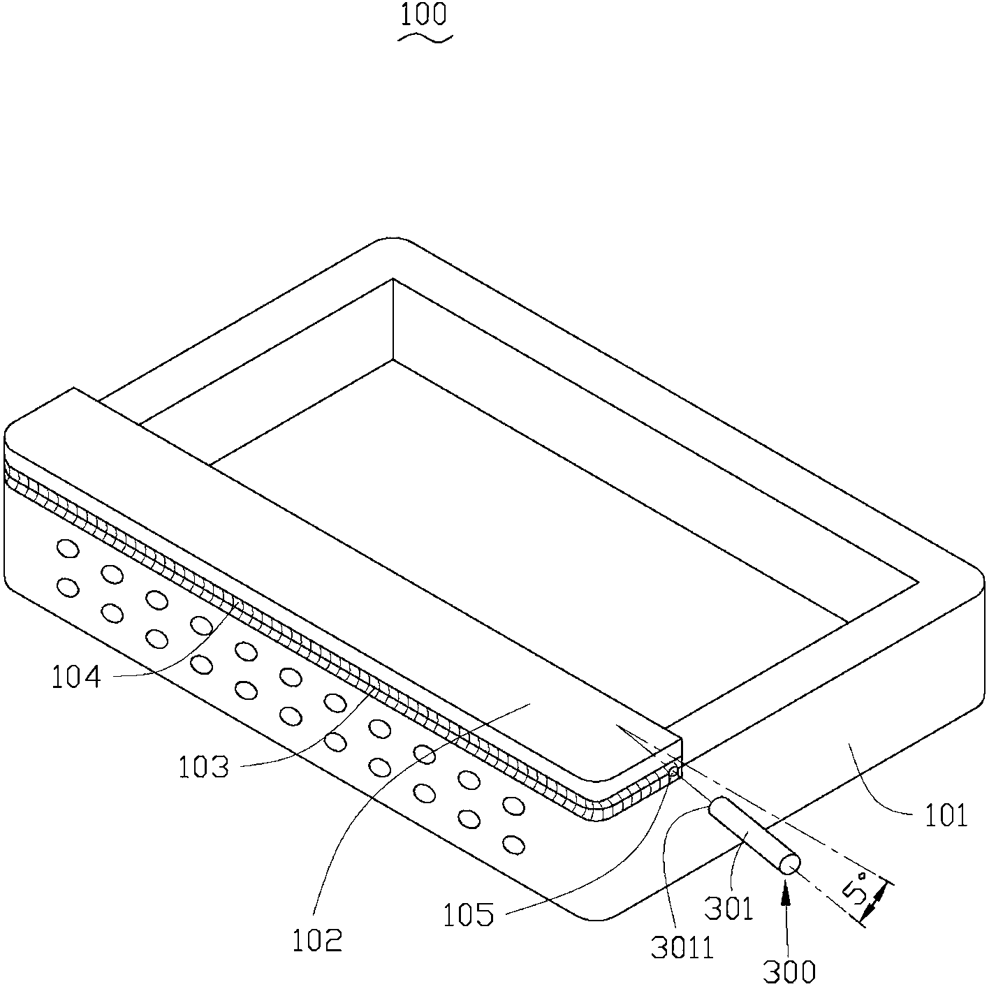
[0018] see figure 1 , the friction stir welding method of the present invention is used to weld two metal elements to join them. In this embodiment, the two metal components are a body 101 and a cover 102 respectively, and the body 101 and the cover 102 are joined by friction stir welding to form a metal shell 100 .

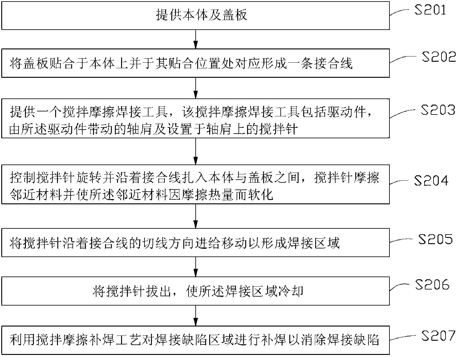
[0019] Please also refer to figure 2 , the friction stir welding method of this embodiment will be described in detail below by taking welding the metal shell 100 as an example.

[0020] In step S201 , the body 101 and the cover 102 are provided. In this embodiment, the body 101 and the cover 102 are made of aluminum alloy.

[0021] In step S202 , attach the cover plate 102 to the body 101 and form a bonding line 103 correspondingly at the attaching position. In this embodiment, the bonding wire 103 is located on the sides of the main body 101 and the cover 102 . A to-be-welded area 104 extending along the joint line 103 is defined at the junction of the co...


PUM

PropertyMeasurementUnit
depthaaaaaaaaaa

Abstract

A stirring friction repair welding process is used for eliminating a welding defect area on a workpiece and comprises the following steps of providing a repair welding tool, wherein the repair welding tool comprises a drive member and a stirring rod which is driven by the drive member, the stirring rod is provided with a working end part, and the distance between two most remote points on the edge of the cross section of the working end part is greater than the maximal diameter of the welding defect area; controlling the stirring rod to rotate and utilizing the working end part to penetrate an adjacent area of the welding defect area; moving the stirring rod along the direction towards the welding defect area so as to completely cover the welding defect area; and unplugging the stirring rod and cooling the welding defect area. The invention also provides a stirring friction welding method adopting the repair welding process. Since the repair welding tool only comprises the drive member and the stirring rod, the manufacturing cost is low, and the procedures and the working time can be saved through the stirring friction repair welding process.

Description

technical field [0001] The invention relates to a repair welding process, in particular to a friction stir repair welding process and a friction stir welding method using the repair welding process. Background technique [0002] Electronic devices generally include metal casings, and some metal casings cannot be formed at one time by die-casting due to structural limitations. Such a metal shell generally includes a body and a cover plate, and the body and the cover plate are joined together by a friction stir welding method to form a metal shell. Friction stir welding typically produces weld defects on the metal shell. For example, when the stirring pin is pulled out by friction stir welding, the softened metal at its periphery flows into the space left after the stirring pin is pulled out. Since the softened metal has a certain viscous effect, the remaining space will not be filled. , so as to produce a certain depression and produce some special-shaped protrusions on the...

Claims


Application Information

Patent Timeline
Patent Type & Authority Applications(China)
IPC IPC(8): B23K20/12
CPCB23K20/12B23K20/122B23P6/00B23K20/1275B23K2203/10B23K20/1255B23K2201/12B23K2101/12B23K2103/10
Inventor 王威珽李俊郎邱郁玟
Owner FU TAI HUA IND SHENZHEN
Why Eureka
Try Eureka