Automatic screw tightening device

A screw and automatic technology, which is applied in metal processing, metal processing equipment, manufacturing tools, etc., can solve the problems that the fuse cover screws cannot be tightened at the same time, the quality of the cover is greatly affected, and the labor intensity of workers is high, so as to reduce the labor force. Effect of labor intensity, quality improvement, reduction of production process and equipment

Inactive Publication Date: 2014-08-20
太仓市凯德防腐科技有限公司
View PDF4 Cites 0 Cited by
  • Summary
  • Abstract
  • Description
  • Claims
  • Application Information

AI Technical Summary

Problems solved by technology

[0002] At present, the fuse cover plates of domestic low-voltage electrical appliance enterprises are manually installed and tightened by a single screw, which cannot realize multiple simultaneous tightening of fuse cover plate screws.
Moreover, due to the manual tightening method, human factors have a greater impact on the quality of the cover plate, and the labor intensity of the workers is high, resulting in low efficiency and unstable quality.

Method used


Image

  • Automatic screw tightening device
  • Automatic screw tightening device

Examples


Embodiment

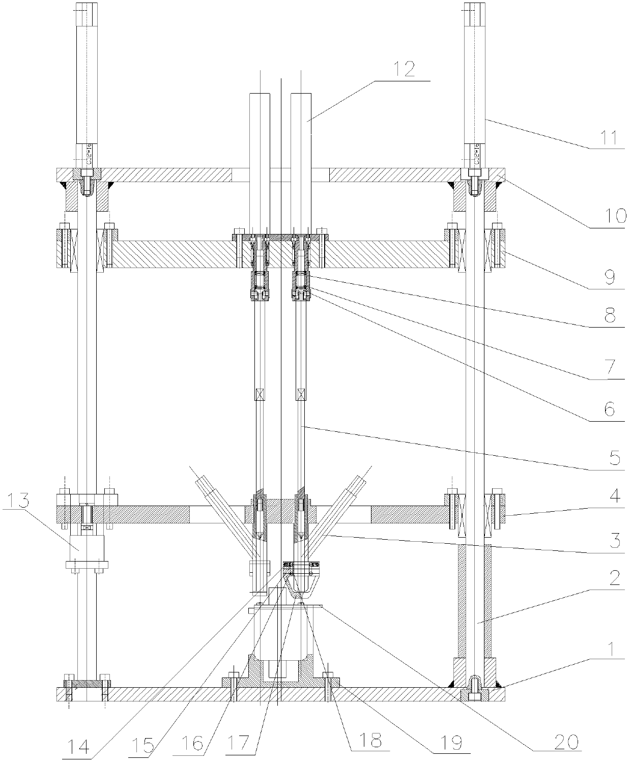
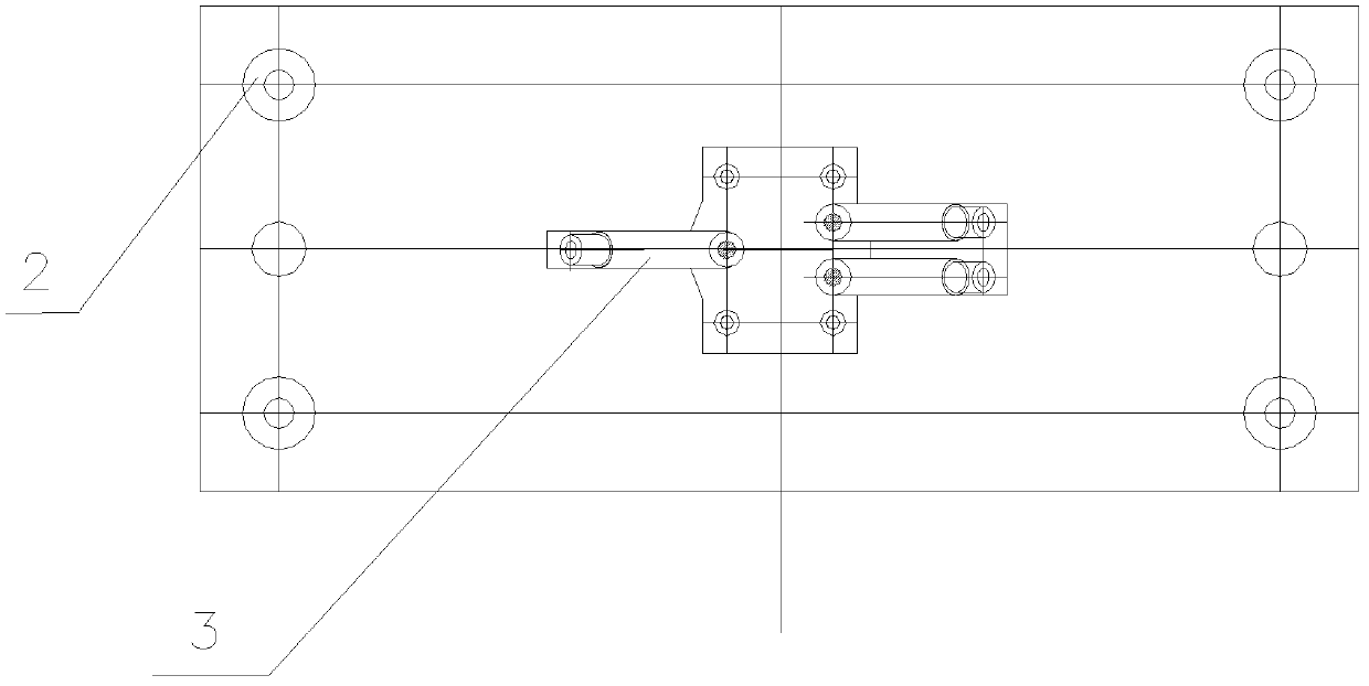
[0027] Such as figure 1 , 2 As shown, an automatic screw tightening device includes frame parts, guide parts, moving tightening parts, screw guide parts and auxiliary parts.

[0028] The frame part includes a base plate 1, an upper cover plate 10 and four circular guide rails 2 connecting the base plate 1 and the upper cover plate 10, and the four circular guide rails 2 parallel to each other provide moving guides for the guide parts and the moving tightening parts.

[0029] Guide parts comprise screw guide bucket 3, moving guide plate 4 and guide cylinder 13, described moving guide plate 4 and guide cylinder all 13 are arranged on the circular guide rail 2, and the piston rod of guide cylinder 13 is arranged on the move guide plate 4, and cylinder body is provided with On the bottom plate 1, the moving guide plate 4 is connected to the guide cylinder 13, and is driven to move up and down along the circular guide rail 2 by the guide cylinder 13. The screw guide barrel 3 is ar...


PUM


Abstract

The invention relates to an automatic screw tightening device which comprises a rack part, a guide part, a moving tightening part, a screw guiding and cutter relieving part and an auxiliary part, wherein the rack part consists of a bottom plate, a round guide rail and an upper cover board; the guide part consists of a moving guide plate, a screw guide barrel and a guide cylinder; the moving tightening part consists of a screwdriver rod, a torque transmission nail, an adjusting spring, a connecting sleeve, a moving plate, a moving cylinder and a pneumatic motor; the screw guiding and cutter relieving part consists of a spring, a lifting pin, a shaft pin, a swing iron and a fixing part; and the auxiliary part consists of a die and a control part. In the working process, a workpiece is fed into the die, a screw is conveyed to the screw guide barrel through a pneumatic conveying device and the screw is guided and limited to be separated from the screw guide barrel through the screw guiding and cutter relieving part. When the screw is tightened, the pneumatic motor of the moving tightening part is inflated to drive the screwdriver rod to rotate through a connecting sleeve and the torque transmission nail, and the moving cylinder is inflated to drive the moving tightening part to move so as to screw the screw tightly. Compared with the prior art, the automatic screw tightening device has the advantages of high efficiency, high quality, wide application range and the like.

Description

technical field [0001] The invention relates to a screw tightening device, in particular to an automatic screw tightening device. Background technique [0002] At present, the fuse cover plates of domestic low-voltage electrical appliance enterprises are manually installed and tightened by a single screw, which cannot realize multiple simultaneous tightening of fuse cover plate screws. Moreover, because the manual tightening method is adopted, human factors have a greater impact on the quality of the cover plate, and the labor intensity of the workers is high, resulting in low efficiency and unstable quality. Contents of the invention [0003] The object of the present invention is to provide an automatic screw tightening device with high efficiency, good quality and wide application range in order to overcome the above-mentioned defects in the prior art. [0004] The purpose of the present invention can be achieved through the following technical solutions: an automatic ...

Claims


Application Information

Patent Timeline
Patent Type & Authority Patents(China)
IPC IPC(8): B23P19/06
Inventor 夏鹏张敏良岳敏钱华
Owner 太仓市凯德防腐科技有限公司
Why Eureka
Try Eureka