Water gap plate for battery case mold and battery case mold

A technology of battery shell and nozzle plate, applied in the field of nozzle plate and battery shell mold, can solve the problems such as deformation of inserts 24, partial glue of battery shell rib 25, and inability to effectively balance the resultant force of inserts 24, so as to reduce the joint force. External force, improve the effect of rib partial glue

Active Publication Date: 2015-07-08
肇庆理士电池技术有限公司 +1
View PDF3 Cites 0 Cited by
  • Summary
  • Abstract
  • Description
  • Claims
  • Application Information

AI Technical Summary

Problems solved by technology

When the battery case 23 is injection molded, the injection pressure of each cavity is different, and the resultant force received by the insert 24 cannot be effectively balanced, so that the insert 24 is deformed by force, and the produced battery case rib 25 is biased, which affects the performance of the battery

Method used


Image

  • Water gap plate for battery case mold and battery case mold
  • Water gap plate for battery case mold and battery case mold
  • Water gap plate for battery case mold and battery case mold

Examples


Embodiment 1

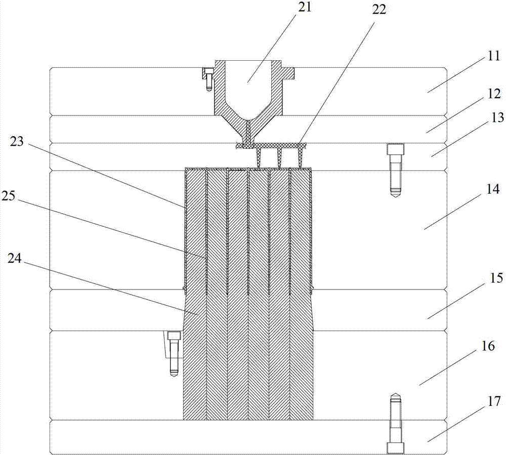
[0023] Please refer to figure 1 ,

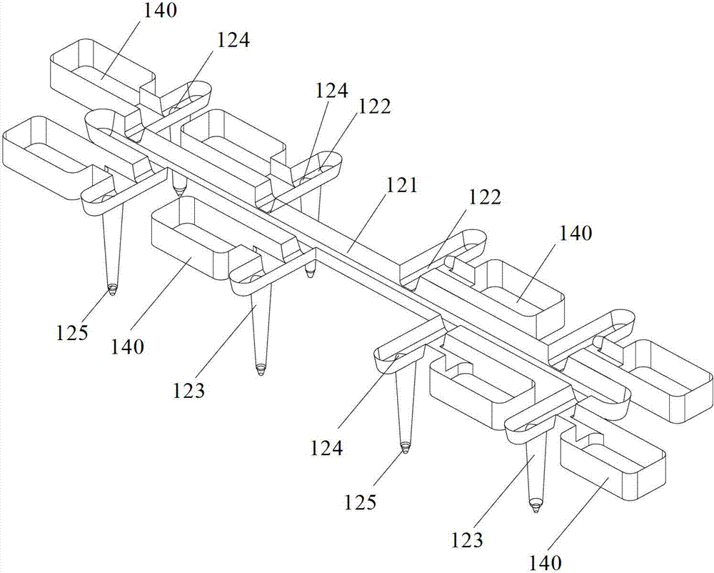
[0024] An embodiment of the nozzle plate 100 for the battery case mold of the present application includes a substrate 110 , a flow channel structure 120 , a flow limiting valve 130 and a flow limiting valve slot 140 , and the flow channel structure 120 is embedded in the substrate 110 . The channel structure 120 includes a main channel 121, a branch channel 122 and a branch pipe 123, the branch channel 122 communicates with the main channel 121, the bottom of the branch channel 122 is provided with a first through hole 124, and the branch pipe 123 is connected to the branch channel through the first through hole 124. 122 communicates, and the lower end of the shunt pipe 123 is provided with a glue inlet point 125 . The restrictor valve 130 includes a fixed part 131 and a restrictor part 132. The fixed part 131 is arranged in the restrictor valve groove 140 and can move in the restrictor valve groove 140. When the fixed part 131 moves, it c...

Embodiment 2

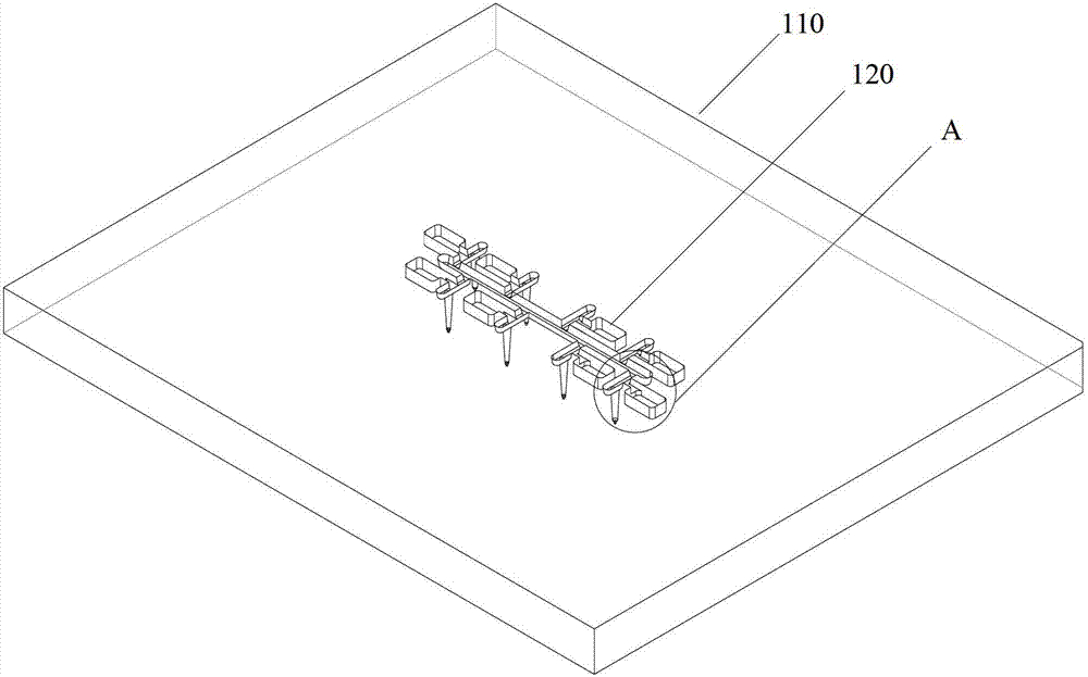
[0031] Please refer to figure 2 ,

[0032] The battery case mold of the present application includes a nozzle plate 100 for the battery case mold, and one embodiment thereof includes a substrate 110, a flow channel structure 120, a flow limiting valve 130 and a flow limiting valve slot 140, and the flow channel structure 120 is embedded in the substrate 110 in. The channel structure 120 includes a main channel 121, a branch channel 122 and a branch pipe 123, the branch channel 122 communicates with the main channel 121, the bottom of the branch channel 122 is provided with a first through hole 124, and the branch pipe 123 is connected to the branch channel through the first through hole 124. 122 communicates, and the lower end of the shunt pipe 123 is provided with a glue inlet point 125 . The restrictor valve 130 includes a fixed part 131 and a restrictor part 132. The fixed part 131 is arranged in the restrictor valve groove 140 and can move in the restrictor valve groove...


PUM


Abstract

The invention discloses a water gap plate for a battery case mold. The water gap plate comprises a base plate and a flow channel structure; and the flow channel structure comprises a main flow channel, a secondary flow channel and a shunting pipe. The water gap plate further comprises a flow limiting valve and a flow limiting valve slot; and the flow limiting valve, which comprises a fixed part and a flow limiting part, is arranged in the flow limiting valve slot, wherein the fixed part can move in the flow limiting valve slot and drive the flow limiting part to move so as to limit the flow of adhesive flowing in an adhesive inlet point. The invention also discloses a battery case mold. According to the water gap plate for the battery case mold, the flow limiting valve and the flow limiting valve slot are adopted, the flow limiting valve is arranged in the flow limiting valve slot and comprises the fixed part and the flow limiting part, the fixed part can move in the flow limiting valve slot and drive the flow limiting part to move, so as to limit the flow of the adhesive flowing in the adhesive inlet point; and the flow limiting valve is arranged on the flow channel structure, so that the flow of the adhesive can be controlled by adjusting the flow limiting valve, the pressure of each cavity can be effectively adjusted, and the total external force on an insert can be reduced, and as a result, the problem that the adhesive is departed from the ribs of a battery case can be solved.

Description

technical field [0001] The application relates to the field of storage battery production, in particular to a nozzle plate used for a battery case mold and a battery case mold. Background technique [0002] The battery case is one of the outer carriers of the battery and is generally made of plastic. The quality of the battery case has a direct or indirect impact on the quality of the battery, so the injection molding quality of the battery case is particularly important. [0003] The battery casings of most batteries have multiple cavities, and adjacent cavities are separated by relatively thin and deep plastic ribs. figure 1 It is a schematic diagram of an existing battery shell mold, including a panel 11, a nozzle push plate 12, a nozzle plate 13, a plate 14, a push plate 15, a fixing plate 16 and a bottom plate 17, and the glue injection hole 21 is arranged on the panel 11 and the nozzle push plate 12 and communicate with the channel structure 22. When the battery cas...

Claims


Application Information

Patent Timeline
Patent Type & Authority Patents(China)
IPC IPC(8): B29C45/30
Inventor 熊正林路俊斗齐国军
Owner 肇庆理士电池技术有限公司
Why Eureka
Try Eureka