Printing device for pannel

A printing device and panel technology, applied in printing, printing machines, rotary printing machines, etc., can solve problems such as no consideration, and achieve the effect of shortening the delivery time

Inactive Publication Date: 2013-02-06
HITACHI LTD
View PDF10 Cites 6 Cited by
  • Summary
  • Abstract
  • Description
  • Claims
  • Application Information

AI Technical Summary

Problems solved by technology

However, in this printing machine, no consideration is given to preventing dust, etc. from adhering to the workpiece before the workpiece is guided to the rotary table.

Method used


Image

  • Printing device for pannel
  • Printing device for pannel
  • Printing device for pannel

Examples


Embodiment Construction

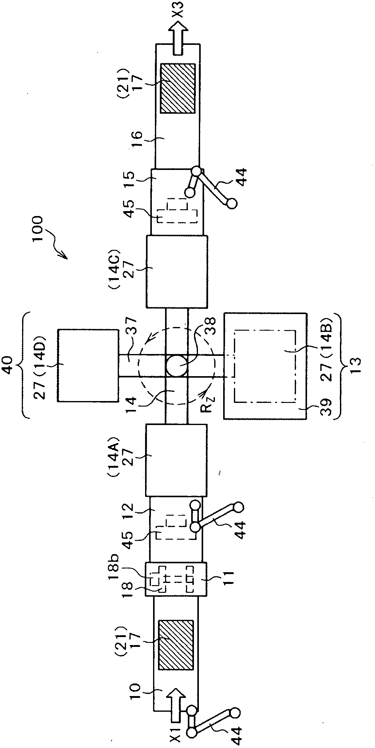
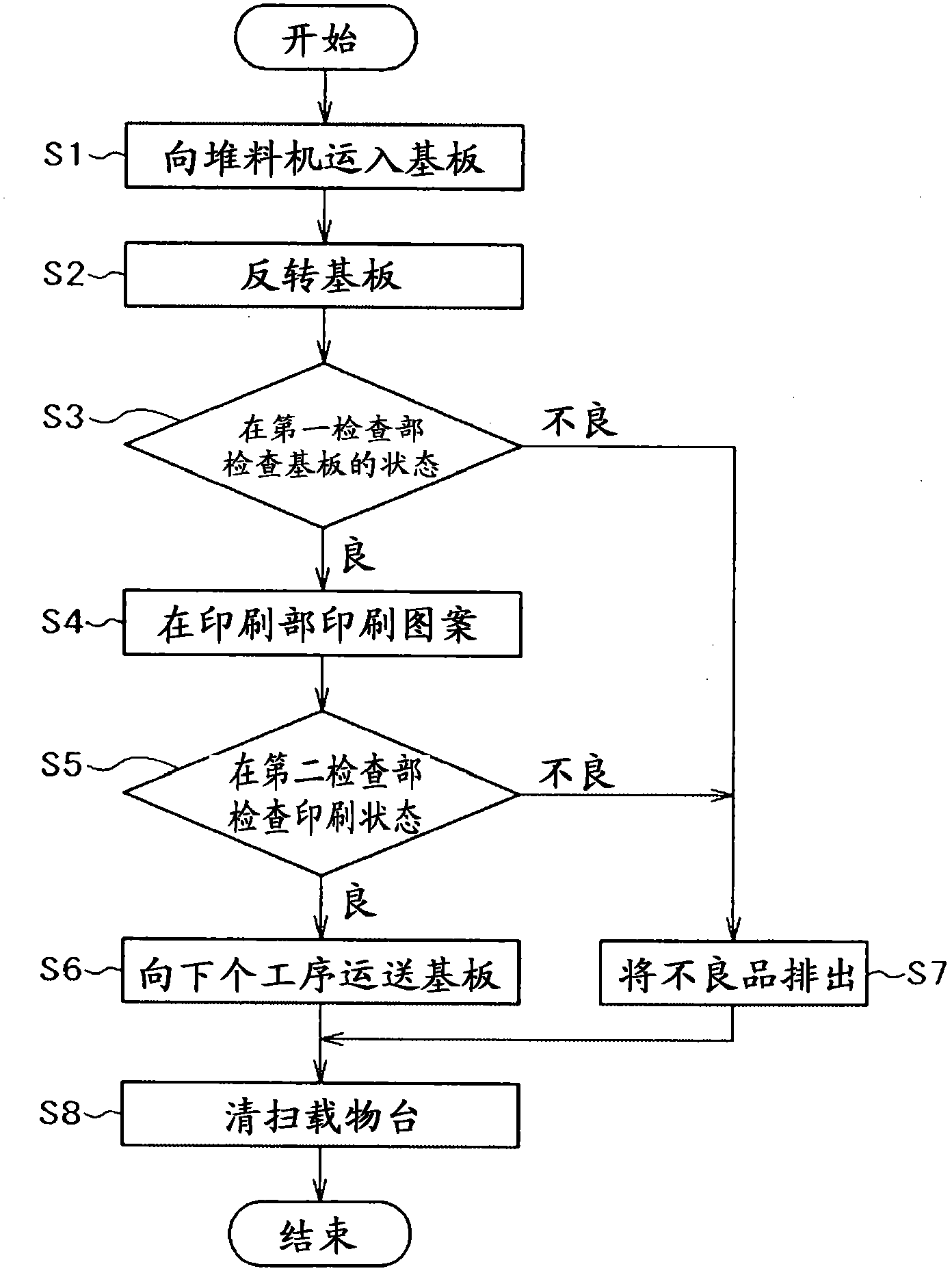
[0023] Next, an embodiment of the panel printing device according to the present invention will be described with reference to the drawings. figure 1 is a top view of an embodiment of the printing device 100 . Between the stocker 10 on the carry-in side in the horizontal direction and the stage conveyor 16 on the carry-out side arranged in a straight line, there are four worktables 14A to 14D arranged at intervals of 90 degrees. workbench14.

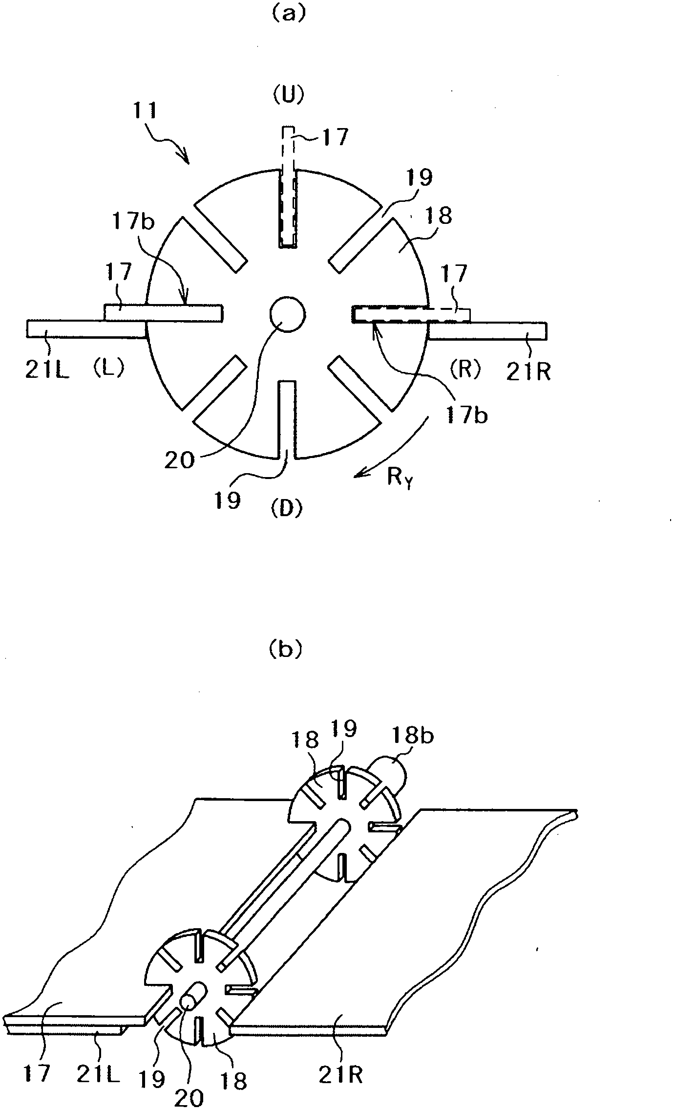
[0024] On the downstream side of the stocker 10 on the carry-in side in the carry-in direction, a substrate reversing mechanism 11 and a first inspection unit 12 , which will be described in detail later, are provided. The second inspection unit 15 is provided between the rotary table 14 and the stage conveyor 16 on the carry-out side. The printing unit 13 is arranged in a direction (X direction) perpendicular to the direction in which the stocker 10 and the stage conveyor 16 are arranged, that is, a direction passing through the cente...


PUM


Abstract

The present invention discloses a printing device for a panel. The technical problem to-be-solved by the present invention is to reduce printing defects caused by dust and the like in the printing device for the panel, and to print at a high speed with high precision. In the present invention, the printing device for the panel (100) forms a predetermined pattern by screen printing on the surface of the substrate (17). The printing is downward by the substrate, and is brought into by a stage conveyor of a stacker part (10). At the end portion of the stacker, a substrate inversion mechanism (11) is arranged to invert the printing surface of the substrate. The substrate being inverted is printed in the printing section (13). A rotary worktable (14) is clamped between the inversion mechanism and the printing section. The substrate is positioned at the printing section by the rotary worktable. In addition, the rotary worktable can move up and down.

Description

technical field [0001] The present invention relates to a panel printing device that prints on a panel and then dries it, and particularly relates to a panel printing device that prints on a panel at high speed. Background technique [0002] As shown in Patent Document 1, a conventional printing apparatus includes a rotary table that rotates intermittently in order to efficiently produce printed matter, and a plate table on which an intaglio plate is placed is fixed to the outer periphery of the rotary table. In addition, a squeegee and a finisher are installed on the plate table. Further, the finisher fills the intaglio plate on the plate table with the ink supplied from the squeegee to the plate table. In addition, the rubber cylinder is moved while rotating between the plate table stopped at a predetermined position and the plate table on which the printed matter is placed. First, the ink is transferred to the rubber cylinder, and then the rubber cylinder is placed on th...

Claims


Application Information

Patent Timeline
Patent Type & Authority Applications(China)
IPC IPC(8): B41F15/26
CPCB41F15/08B41F15/26B41F21/106B41F33/0036B41F33/0081B41F35/003H05K3/12H05K3/34
Inventor 和田正文引地圭桥本尚明矢作睦行本间真
Owner HITACHI LTD
Why Eureka
Try Eureka