Pipe discharge mechanism

A discharge mechanism and pipe technology, applied in the direction of conveyor objects, transportation and packaging, rollers, etc., can solve the problems of inconvenient discharge and transportation, easy rolling of pipes, and unfixable positions, etc., so as to achieve convenient and flexible use and improve efficiency Effect

Inactive Publication Date: 2013-02-06
WUXI HUALIAN SCI & TECH GROUP
View PDF10 Cites 14 Cited by
  • Summary
  • Abstract
  • Description
  • Claims
  • Application Information

AI Technical Summary

Problems solved by technology

[0002] Before the present invention was made, in the prior art, most of the pipes were conveyed by rollers, so that not only the position could not be fixed, but also the pipes were easy to roll, and the discharge and transportation were very inconvenient, and it was difficult to meet the production needs

Method used


Image

  • Pipe discharge mechanism
  • Pipe discharge mechanism
  • Pipe discharge mechanism

Examples


Embodiment Construction

[0014] The present invention will be further described below in conjunction with specific drawings and embodiments.

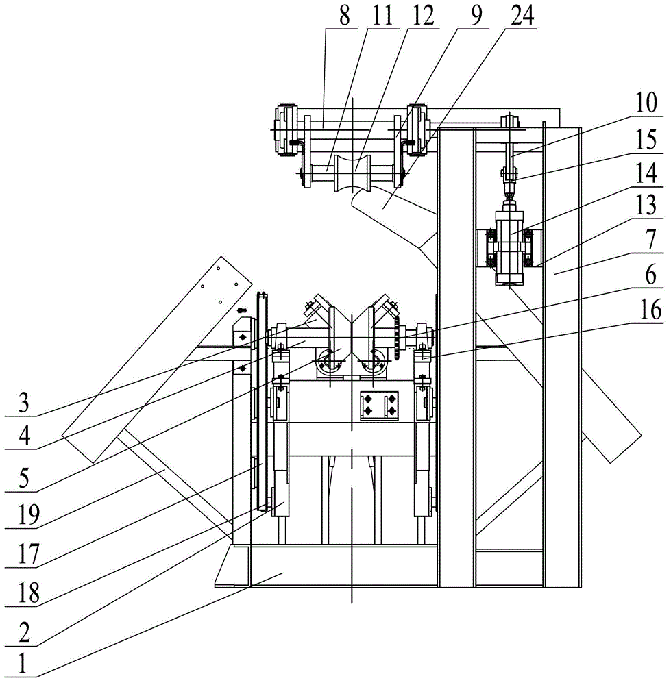
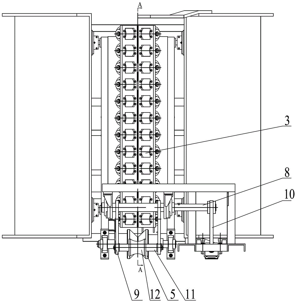
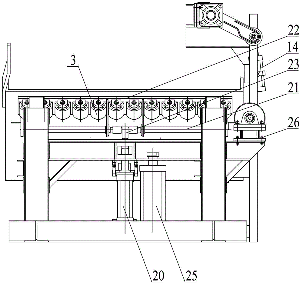
[0015] As shown in the figure: the pipe discharge mechanism is vertically slid on the installation seat 1 and installed with a lifting frame 2, and the rotating frame on the lifting frame 2 is provided with a roller shaft 4, and a conveying roller 5 and a drive are fixed on the roller shaft 4. Sprocket 6, two rows of driven rollers 3 on the left and right are installed in the rotation of lifting frame 2 on the rear side of conveying roller 5, and left and right two rows of driven rollers 3 form a V-shaped conveying groove, and driven roller 3 cooperates with conveying roller 5; Mounting seat 1 is fixed with hold-down frame 7, is provided with hold-down pivot 8 at the top end portion rotatable frame of hold-down frame 7, is fixed with pivot frame 9 and cylinder lever 10 on hold-down pivot 8, on pivot frame Rotate on 9 and be equipped with compression wheel shaft...


PUM


Abstract

The invention relates to a pipe discharge mechanism. A lifting support is installed on an installation base in a vertically sliding mode, a roller shaft is rotatably erected on the lifting support, a conveying roller and a drive sprocket are fixed on the roller shaft, left and right rows of driven rollers are rotatably installed on the lifting support arranged on the rear side of the conveying roller, a compression support is fixed on the installation base, a compression pivot shaft is rotatably erected on the top end portion of the compression support, a pivot shaft frame and an air cylinder lever are fixed on a compression pivot shaft, a compression wheel shaft is rotatably installed on the pivot shaft frame, a compression wheel is fixed on the compression wheel shaft, an air cylinder base is fixed on the compression support, a compression air cylinder is installed on the air cylinder base in a hinged connection mode, and an air cylinder head is fixed on the end portion of a piston rod of the compression air cylinder. The pipe discharge mechanism has the advantages that the pipe discharging efficiency is improved and the usage is convenient and flexible.

Description

technical field [0001] The invention relates to a pipe discharging mechanism, which belongs to the technical field of mechanical equipment. Background technique [0002] Before the present invention was made, in the prior art, the discharge of pipes was mostly conveyed by rollers, so that not only the position could not be fixed, but also the pipes were easy to roll, and the discharge and transportation were very inconvenient, and it was difficult to meet the production needs. Contents of the invention [0003] The purpose of the present invention is to overcome the deficiencies in the prior art, and provide a pipe discharge mechanism that can ensure the fixed position of the pipe during the discharge conveying process and improve the discharge efficiency of the pipe. [0004] According to the technical solution provided by the present invention, the pipe discharge mechanism is vertically slidably installed with a lifting frame on the mounting base, and a roller shaft is a...

Claims


Application Information

Patent Timeline
Patent Type & Authority Applications(China)
IPC IPC(8): B65G13/07B65G13/12B65G47/22
Inventor 陈飞吴云强李秀成龚国华周怡殷佳燕周洪根曹益民钱军
Owner WUXI HUALIAN SCI & TECH GROUP
Why Eureka
Try Eureka