Pneumatic stock line conveying system

A technology of conveying system and sending system, which is applied in the direction of conveyor, conveying bulk materials, transportation and packaging, etc. It can solve the problems of inability to realize long-distance transportation, small conveying capacity of traditional pipe chains, and inflexible pipe layout, etc., and achieve material saving Low cost, flexible pipe layout, and reduced difficulty in construction operations

Inactive Publication Date: 2021-08-24
上海润牧机电设备有限公司
View PDF0 Cites 0 Cited by
  • Summary
  • Abstract
  • Description
  • Claims
  • Application Information

AI Technical Summary

Problems solved by technology

[0005] The purpose of the present invention is to provide a pneumatic material line conveying system to solve the problem that the existing central pipe chain proposed in the above background technology needs multi-loop overlapping when conveying through the pneumatic material line, which cannot realize long-distance conveying, and the traditional The transportation volume of the pipe chain is small, the cost is very high, and the pipe layout is not flexible enough

Method used


Image

  • Pneumatic stock line conveying system
  • Pneumatic stock line conveying system
  • Pneumatic stock line conveying system

Examples


Embodiment Construction

[0024] The following will clearly and completely describe the technical solutions in the embodiments of the present invention with reference to the accompanying drawings in the embodiments of the present invention. Obviously, the described embodiments are only some, not all, embodiments of the present invention.

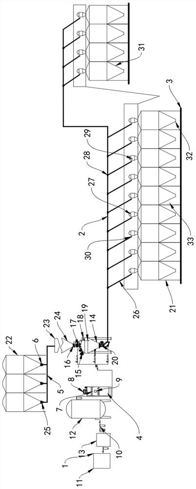
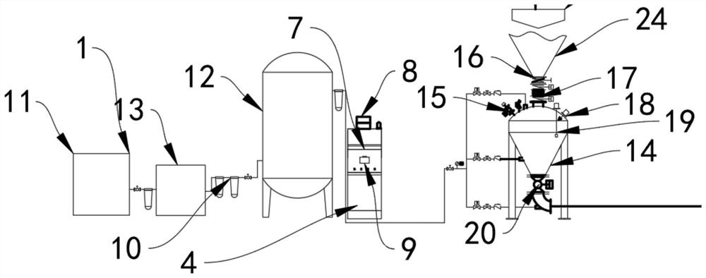
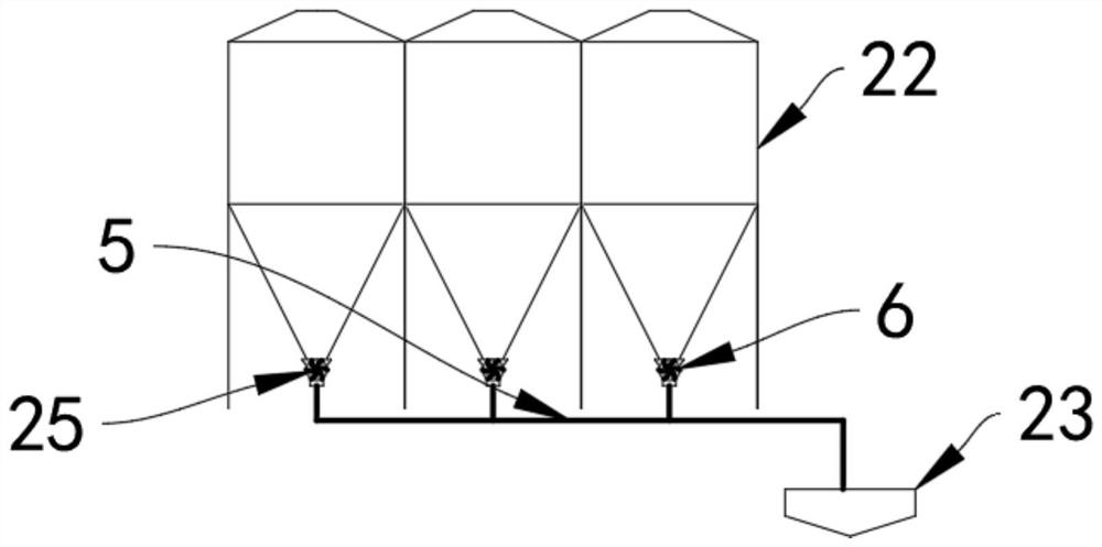
[0025] see Figure 1-5 , an embodiment provided by the present invention: a pneumatic material line conveying system, including a sending system 1, a conveying system 2, a blanking system 3, and a control system 4, characterized in that: one side of the sending system 1 is equipped with a pneumatic machine 11, one end of the conveying system 2 is provided with a conveying pipeline 26, the interior of the blanking system 3 is provided with an end buffer 31, and the interior of the control system 4 is provided with a control cabinet 8. The pipe is connected to the gas storage tank 12, and the gas storage tank 12 is connected to the freeze dryer 13 with a high-pressure ...


PUM


Abstract

The invention discloses a pneumatic stock line conveying system, relates to the technical field of pneumatic stock line conveying, and aims at solving the problems that when an existing central pipe chain is conveyed through a pneumatic stock line, multi-loop lap joint is needed, long-distance conveying cannot be achieved, and a traditional pipe chain is small in conveying amount, very high in cost and not flexible enough in pipe distribution. An air compressor is installed on one side of a sending system, a conveying pipeline is arranged at one end of the conveying system, an end point buffer is arranged in a discharging system, a control cabinet is arranged in a control system, a freeze dryer is arranged on one side of the air compressor, an air storage tank is installed on one side of the freeze dryer, a sending pump is arranged on one side of the air storage tank, a filter set is installed at one end of the air storage tank, and the filter set is connected with one end of the air storage tank in a welded mode.

Description

technical field [0001] The invention relates to the technical field of pneumatic material line conveying, in particular to a pneumatic material line conveying system. Background technique [0002] The application of pneumatic material line conveying system in pig farms makes pig farms centralized and technological. In order to better develop pig farms and ensure biological safety, the most effective solution is to reduce or even block people and things Direct or indirect contact with pigs, feed is indispensable to the pig farm every day, so it is necessary to configure the main feed tower far away from the pig farm as a transfer, to avoid people and feed trucks entering the pig farm, but the traditional pipe chain transportation The farthest straight-line conveying distance is less than 200 meters, requiring multi-circuit overlapping, so the system failure rate is high and long-distance conveying cannot be realized at the same time. [0003] When the existing central pipe c...

Claims


Application Information

Patent Timeline
Patent Type & Authority Applications(China)
IPC IPC(8): B65G53/16B65G53/52B65G53/46B65G53/66B65G53/36B65G53/34F26B5/06
CPCB65G53/16B65G53/34B65G53/36B65G53/46B65G53/52B65G53/66F26B5/06
Inventor 杨焕利
Owner 上海润牧机电设备有限公司
Why Eureka
Try Eureka