
Pressure and temperature control system

A pressure temperature, control system technology, applied in the field of water treatment, can solve problems such as unintuitive, short service life of differential pressure switch, non-interchangeable, etc., and achieve the effect of reasonable structure

Inactive Publication Date: 2015-08-19
CHONGQING MOLECULAR WATER SYST
View PDF9 Cites 0 Cited by
  • Summary
  • Abstract
  • Description
  • Claims
  • Application Information

AI Technical Summary

Problems solved by technology

[0004] The inventors of the present invention found that: 1. The differential pressure switch can set the upper and lower pressure limits, but it cannot display the actual pressure value of the current delivery pipeline, which is not intuitive; 2. The differential pressure switch is mechanical, with a spring inside. After using for a period of time, the spring will be damaged and the monitoring pressure value will be inaccurate
Especially in the case of high frequency of start and stop, the service life of the differential pressure switch is shorter
Therefore, in practical applications, commonly used pressure transmitters are used together with pressure monitors; 3. Both pressure transmitters and temperature sensors can only sense the current pressure or temperature, and neither can set the upper limit, lower limit or upper limit of temperature. , low limit, and cannot display the current pressure or temperature value, it needs to be used in conjunction with a pressure monitor or temperature monitor
At this time, the pressure monitor can only be used with the pressure transmitter, and the temperature sensor can only be used with the temperature monitor and cannot be interchanged

Method used


Image

  • Pressure and temperature control system
  • Pressure and temperature control system
  • Pressure and temperature control system

Examples


Embodiment Construction

[0023] In order to make the technical means, creative features, goals and effects achieved by the present invention easy to understand, the present invention will be further described below in conjunction with specific illustrations.

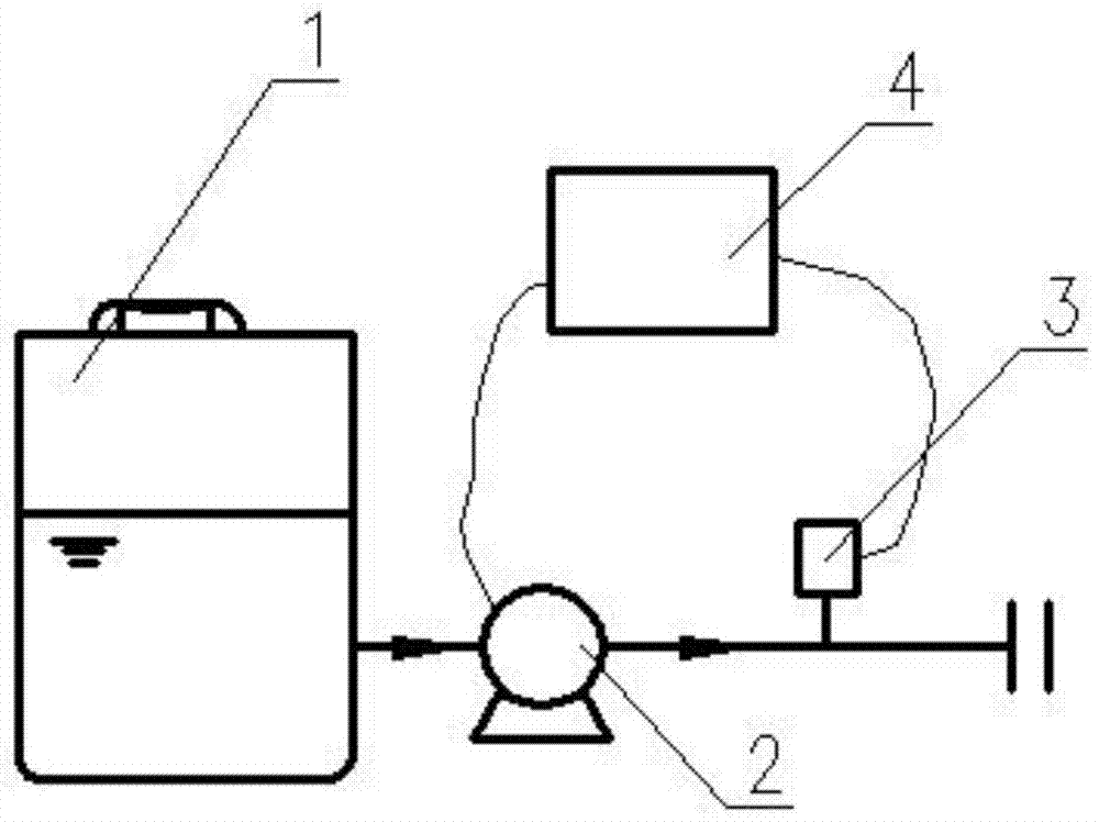
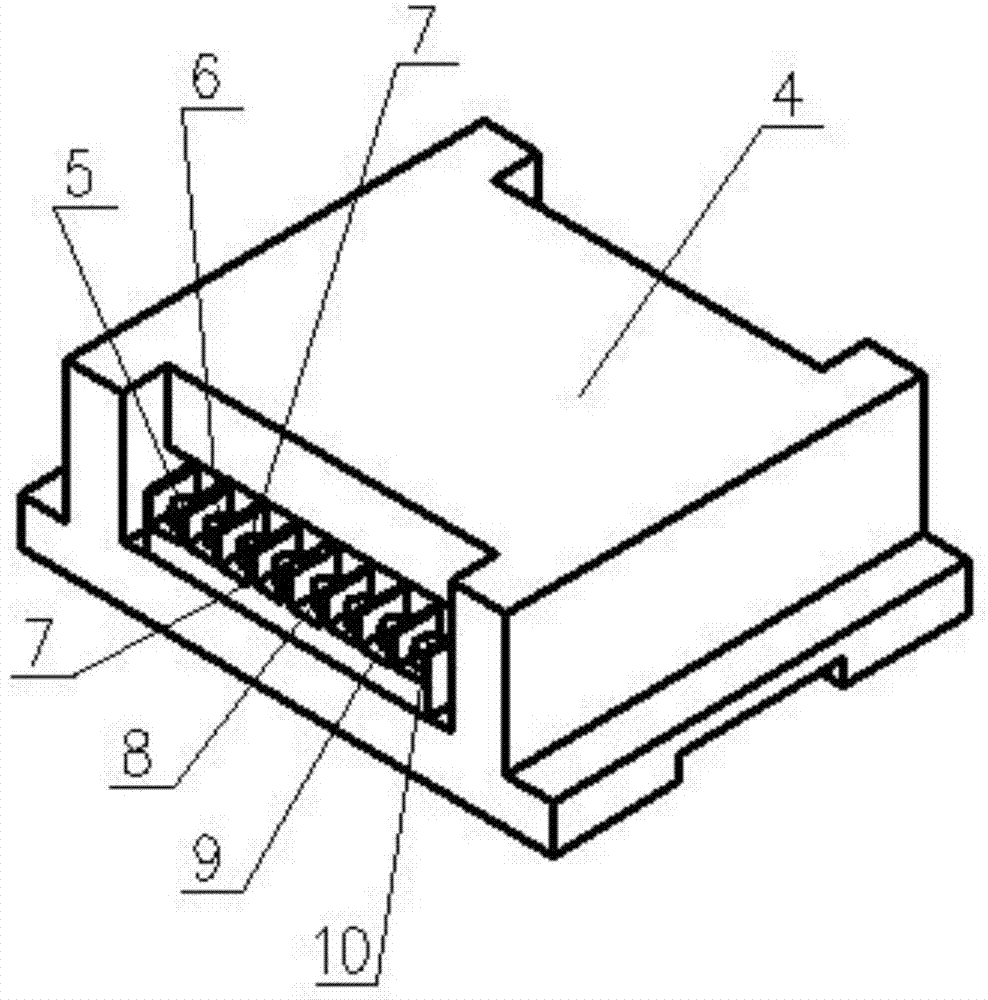
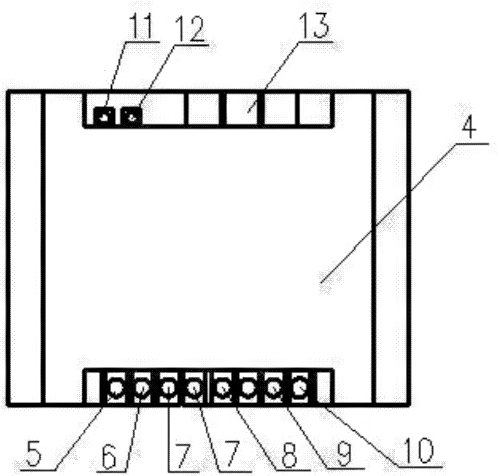
[0024] Such as figure 1 As shown, the present invention includes a water tank 1, a delivery pump 2, a pressure / temperature sensor 3 and a pressure-temperature integrated control box 4. The water tank 1 and the delivery pump 2 are connected to the water end through pipelines in turn, and the water end is connected to a A pressure / temperature sensor 3 and a pressure-temperature integrated control box 4, the signal input end of the pressure-temperature integrated control box 4 is connected to the pressure / temperature sensor 3, and the signal output end of the pressure-temperature integrated control box 4 is connected to the transmission Pump 2 is connected.

[0025] When the water point needs to control the water pressure, the water in the water t...


PUM


Abstract

The invention provides a pressure and temperature control system. The pressure and temperature control system comprises a water tank, a conveying pump, a pressure / temperature sensor and a pressure and temperature integrated control box; the water tank and the conveying pump are sequentially connected to a water using end through pipes, the water using end is sequentially connected with the pressure / temperature sensor and the pressure and temperature integrated control box, the signal input end of the pressure and temperature integrated control box is connected with the pressure / temperature sensor, and the signal output end of the pressure and temperature integrated control box is connected with the conveying pump. By means of the technical scheme, the pressure and temperature control system has the beneficial effect of being reasonable in structure; the high-limit pressure, the low-limit pressure, the high-limit temperature and the low-limit temperature of water in the conveying pipe can be set; actual pressure values or temperature values of the water in the current conveying pipe can be displayed in real time, and conveying of the water in the pipe is controlled.

Description

technical field [0001] The invention belongs to the technical field of water treatment, in particular to a water pressure and temperature control system. Background technique [0002] At present, in order to realize the pressure control of water, differential pressure switches and pressure transmitters are commonly used to monitor the pressure of the pipeline. The pressure transmitter converts the actual pressure value into a usable output signal and feeds it back to the pressure monitor. In order to realize the temperature control of water, a temperature sensor is commonly used, which can sense the temperature of the liquid and convert it into a usable output signal, and then feed it back to the temperature monitor to display the current temperature. [0003] When using a differential pressure switch, you can set the upper and lower pressure limits, and then control the on-off of the circuit through the differential pressure range. When using a pressure transmitter, the a...

Claims


Application Information

Patent Timeline
Patent Type & Authority Applications(China)
IPC IPC(8): E03B1/00E03B7/07E03B7/09E03B11/16
Inventor 马兵
Owner CHONGQING MOLECULAR WATER SYST
Learn More