
Belt flattening mechanism

A technology with strips and parallel axes, which is applied in the field of battery cell manufacturing and battery manufacturing equipment. It can solve the problems of reduced deviation correction accuracy and inability to completely eliminate the wave at the edge of the pole piece, so as to improve accuracy, eliminate waves, and eliminate the edge of the pole piece. The effect of accurate position

Active Publication Date: 2015-10-21
DONGGUAN ARECONN PRECISION MACHINERY
View PDF11 Cites 0 Cited by
  • Summary
  • Abstract
  • Description
  • Claims
  • Application Information

AI Technical Summary

Problems solved by technology

The deflection correction sensor in the prior art is generally directly installed between the two passing rollers, and its disadvantage is that due to the defect of the material of the pole piece or the influence of several previous processes during the movement of the material belt, the pole piece After the tension is tightened, the wave on the edge of the pole piece cannot be completely eliminated, and the point measured by the deviation correction sensor is the edge of the pole piece, which reduces the accuracy of deviation correction

Method used


Image

  • Belt flattening mechanism
  • Belt flattening mechanism
  • Belt flattening mechanism

Examples


Embodiment Construction

[0015] In order to further illustrate the principle and structure of the present invention, preferred embodiments of the present invention will now be described in detail with reference to the accompanying drawings.

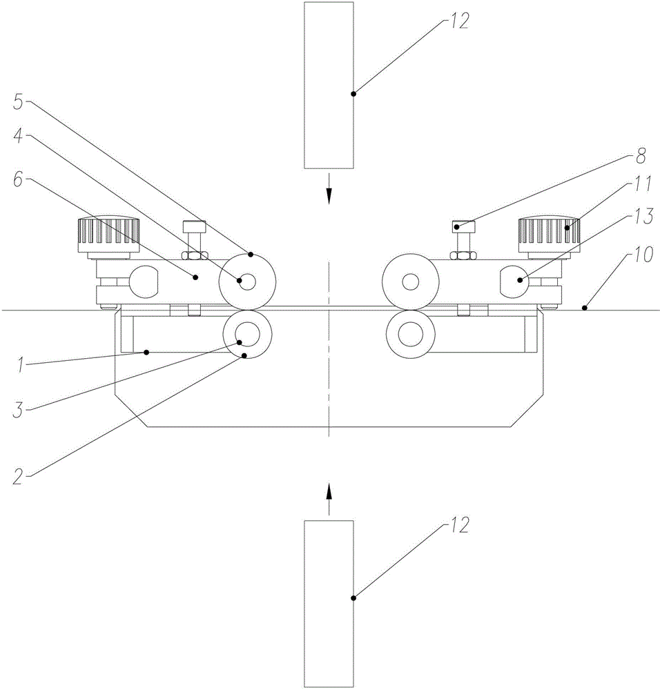
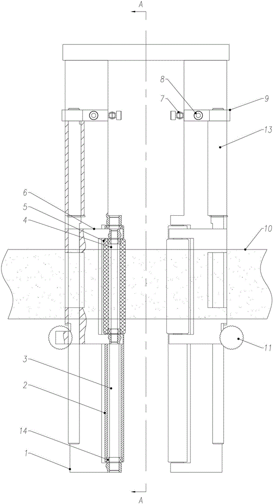
[0016] figure 1 It is the front view of the flattening mechanism embodiment of the strip of the present invention, figure 2 is a top view of the embodiment, image 3 is the left side view of the embodiment.

[0017] The embodiment of the flattening mechanism of the material belt of the present invention is provided with two sets of mechanisms correspondingly, and each set of mechanisms can be divided into a rolling part and a loading part. This structure can realize the function of flattening the strip of the pole piece, and improve the accuracy of the origin position of the deviation correction detected by the through-beam sensor, thereby improving the winding accuracy.

[0018] As shown in the figure, the rolling part is provided with a lower pressing rolle...


PUM


Abstract

A belt unfolding mechanism comprises a rolling part and a loading part, wherein the rolling part is provided with a lower compression roller and an upper compression roller which are axially parallel and raidally correspond to each other, and the lower compression roller and the upper compression roller respectively act on the front side and the back side of a belt; the loading part is provided with a torsion shaft which drives the upper compression roller of the rolling part and provides torque for the upper compression roller to press the belt; and the torsion shaft is basically parallel to the compression rollers. The rolling part comprises a base and a compression roller support, wherein the base is positioned on the back side of the belt, and the lower compression roller is installed on the base; and the compression roller support is connected to the torsion shaft of the loading part, is arranged on the front side of the belt, is provided with the upper compression roller and is used for converting the torque which is transferred by the torsion shaft into compression force which is from the upper compression roller and acts on the front side of the belt. The loading part comprises a loading swing arm and an extension spring, wherein the root part of the loading swing arm is fixed on one end of the torsion shaft; and the extension spring provides the torque for the torsion shaft. The upper compression roller provides the compression force, so that a pole piece can be unfolded; the waves on the edge of the pole piece are eliminated, so that a pole piece edge position which is detected by an inductor is accurate; and thus, the correction detection accuracy is improved, and the belt running accuracy is increased.

Description

technical field [0001] The invention relates to the technical field of battery manufacturing equipment, in particular to the technical field of battery cell manufacturing, and in particular to a flattening mechanism for a material strip used for cell pole pieces. Background technique [0002] With the development of various electronic devices, the use of lithium batteries is becoming more and more widespread, and the demand for lithium batteries is increasing, which puts forward higher requirements for the production machinery of lithium batteries. [0003] In the production process of lithium batteries, the strips of battery pole pieces need to be constantly corrected during the operation of the equipment. The deflection correction sensor in the prior art is generally directly installed between the two passing rollers, and its disadvantage is that due to the defect of the material of the pole piece or the influence of several previous processes during the movement of the ma...

Claims


Application Information

Patent Timeline
Patent Type & Authority Patents(China)
IPC IPC(8): B65H23/34H01M4/04
CPCY02E60/10
Inventor 赵伟
Owner DONGGUAN ARECONN PRECISION MACHINERY
Learn More