Rolling equipment and rolling method

A technology of rolling equipment and rolls, which is applied in the field of rolling mills, can solve the problems of large lateral force component of rolling force, large lateral bending tendency, and large biting angle of foil 3, so as to increase rigidity, improve lubrication conditions, Effect of reducing rolling defects

Active Publication Date: 2021-07-16
SHANGHAI WUXING COPPER CO LTD +1
View PDF13 Cites 0 Cited by
  • Summary
  • Abstract
  • Description
  • Claims
  • Application Information

AI Technical Summary

Problems solved by technology

[0005] The diameter of the work roll has an impact on the rolling of the foil. The smaller the diameter of the work roll, the more conducive to the thinning of the foil, but it also brings Here comes the problem: as shown in Figure 2, in the figure The small-diameter work roll on the left has a small diameter and low rigidity, a large bite angle to the foil 3, and a large lateral component of the rolling force, so it has a large lateral bending tendency
From the above, it can be seen th

Method used


Image

  • Rolling equipment and rolling method
  • Rolling equipment and rolling method
  • Rolling equipment and rolling method

Examples


Embodiment 1

[0043] A rolling equipment used for high-precision rolling of copper foil with a thickness of 0.1mm and a width of 1000mm. The rolling equipment includes a rolling mill and a set of adjustment rolls, which will be described in detail below.

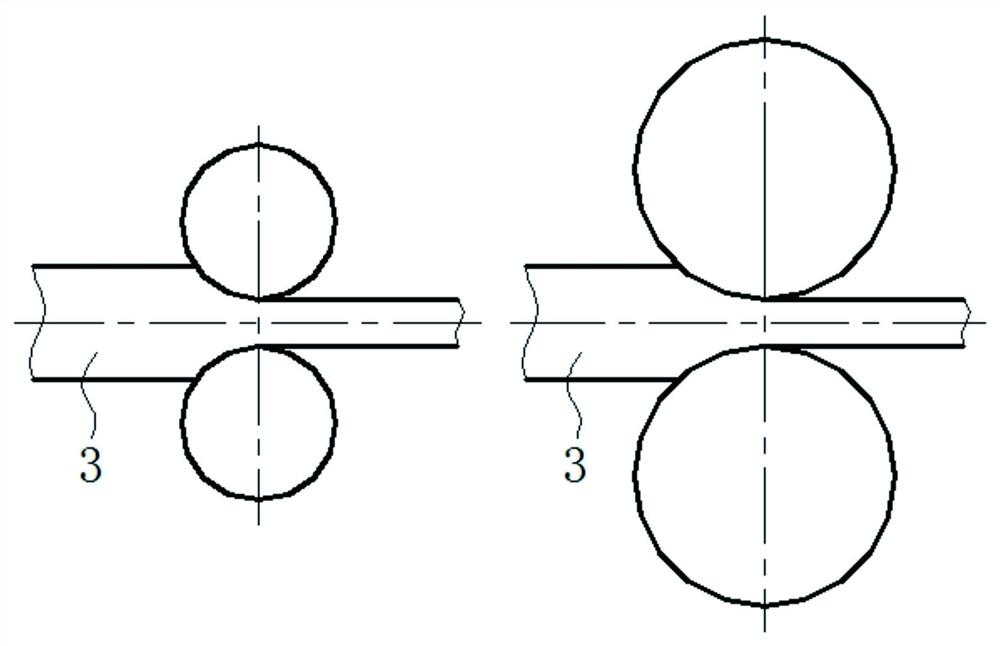
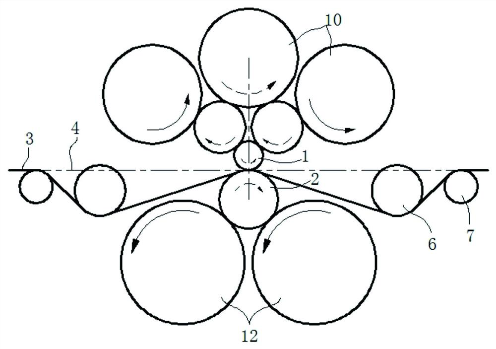
[0044] Such as image 3 As shown, the rolling mill used is a nine-roll rolling mill, and the rolls of the rolling mill are bounded by the rolling center line 4, and are divided into an upper half-roll system and a lower half-roll system, wherein the lower half-roll system consists of a lower work roll 2 and two The lower oblique pressure support roll 12 is formed, and the lower oblique pressure support roll 12 is used to press the lower work roll 2 , and the roll diameter of the lower oblique pressure support roll 12 is larger than that of the lower work roll 2 . The upper half roll system is composed of one upper working roll 1 and five upper oblique support rolls 10 . The roll diameter of the upper work roll 1 in the upper half roll s...

Embodiment 2

[0060] The difference between this embodiment and Embodiment 1 is that it is used for rolling copper foil materials with a thickness of 0.03 mm and a width of 800 mm. Due to the reduction in the thickness of the copper foil, it is necessary to use a smaller diameter upper work roll. In this embodiment, the roll diameter of the upper work roll 1 in the upper half roll set is 60 mm, the structure of the lower half roll set remains unchanged, the roll diameter of the lower work roll 2 in the lower half roll set is still 200 mm, and the lower work roll 2 is still 200 mm in diameter. The roll diameter of the roll 2 is approximately 3.3 times the roll diameter of the upper work roll 1 .

[0061] In order to make up for the lack of rigidity caused by the reduction of the diameter of the upper work roll 1, such as Figure 10 As shown, the rolling mill used is a thirteen-high rolling mill, and the structure of the lower half of the rolling mill is unchanged, while the upper half of th...

Embodiment 3

[0064] In this embodiment, the rolling mill is a nine-high rolling mill. Such as Figure 11 As shown, the upper half roll system of the rolling mill is the same as the upper half roll system in Example 1, the number of rolls in the lower half roll system is also three, and the roll diameter of the lower work roll 2 is still 2 times that of the upper work roll 1. times. The difference from Example 1 is that the lower half roll system is composed of a lower working roll 2 arranged in a straight line, a lower direct pressure backup roll 11 with a small roll diameter and a lower direct pressure backup roll 11 with a large roll diameter , wherein the lower direct pressure backup roll 11 with a small roll diameter is used to press the lower work roll 2, and the lower direct pressure backup roll 11 with a large roll diameter is used to press the lower direct pressure backup roll 11 with a small roll diameter. The flattening rolls 6 can be brought closer to the work rolls due to the...


PUM


Abstract

Rolling equipment comprises a rolling mill and an adjusting roller set. The rolling mill adopts a rolling scheme of working rollers with unequal diameters, so that the thinning of foil is generally facilitated, and a better plate shape is also favorably obtained; and the rolling mill adopts an asymmetric roller system, so that the number of rollers is reduced, the precision of the roller system is favorably improved, and the rollers are convenient to adjust and maintain. The adjusting roller set adopts oil blocking rollers and flattening rollers which are unequal in diameter, the flattening function and the oil blocking function are both considered, the oil blocking rollers with the smaller roller diameter are beneficial to squeezing away redundant lubricating oil, and the flattening rollers with the larger roller diameter are beneficial to reducing the original defects of the foil. According to the rolling method, the height of the flattening rollers is adjusted, the foil is wrapped on the roller surface of the working roller with the larger roller diameter to form a wrapping arc, and tension is evenly distributed on the cross section of the foil through back supporting of the working roller on the foil; and the defects are eliminated in the key forming initial stage of rolling, and the plate shape is stabilized in the later stage of rolling forming, so that high-precision rolling of the wide foil is achieved.

Description

technical field [0001] The invention relates to the technical field of rolling mills, in particular to rolling equipment and a rolling method for high-precision rolling of wide-width foils. Background technique [0002] With the advancement of the technology industry, the market demand for high-precision wide-width foils is becoming more and more urgent. Under the current technical background, the rolling technology for wide-width and thick foils is basically mature, but there are still many technical obstacles in the rolling technology of high-precision wide-width foils. For thicker foils, even if there are shape defects after rolling, the shape can still be corrected by tension leveling or other flattening means. For foils, especially those with extremely small thickness, due to the lack of subsequent The means of shape correction can only be controlled by rolling. Especially for foils with high deformation resistance such as copper, copper alloys, and stainless steel, i...

Claims


Application Information

Patent Timeline
IPC IPC(8): B21B1/40B21B13/02B21B27/02B21B29/00B21B37/28B21B45/02B21B37/48B21B37/68B21B39/16
CPCB21B1/40B21B13/023B21B27/021B21B29/00B21B37/28B21B45/0284B21B37/48B21B37/68B21B39/16
Inventor 刘洪勤马力徐继玲李毅
Owner SHANGHAI WUXING COPPER CO LTD
Why Eureka
Try Eureka