Wide strip foil rolling equipment

A rolling equipment and strip foil technology, which is applied in the field of foil rolling mills and high-precision wide-width metal strip rolling, can solve problems such as low rigidity, unsuitable for thin rolling, and large biting angle of strip foil 5, so as to solve curling Deformation problem, improve production efficiency, good oil blocking effect

Active Publication Date: 2021-07-16
SHANGHAI WUXING COPPER CO LTD +1
View PDF5 Cites 1 Cited by
  • Summary
  • Abstract
  • Description
  • Claims
  • Application Information

AI Technical Summary

Problems solved by technology

As we all know, the smaller the diameter of the work roll, the more favorable the thinning of the strip foil 5, but it also brings problems: in Figure 4, the diameter of the left working roll is small, the rigidity is small, the bite angle of the strip foil 5 is large, and the lateral component of the rolling force is large. Therefore, its lateral bending tendency is large
To sum up, the small-diameter work rolls are good for thinning, but limited by the difficulty in controlling the rolled strip shape, so the rolling width should not be too large; while the large-diameter work rolls are conducive to the control of the rolled strip shape and are suitable for rolling. Wide, but not suitable for rolling thin
For wide strip foil with a thickness of less than 0.3mm, the diameter of the work roll must be small enough (usually 25-50mm in diameter) to obtain a large amount of rolling reduction, and the shape of the plate at this time will be very difficult to control

Method used


Image

  • Wide strip foil rolling equipment
  • Wide strip foil rolling equipment
  • Wide strip foil rolling equipment

Examples


Embodiment 1

[0048] A wide-width strip and foil rolling equipment is used for rolling copper alloy strip and foil. The final rolling thickness of the copper alloy strip and foil is 0.1mm and the width is 1000mm. The boundary thickness of the strip and the foil is 0.15mm, and the thickness of the copper alloy strip and foil (hereinafter referred to as the strip foil) already belongs to the foil. Due to the high deformation resistance of copper alloy, it is difficult to ensure the flatness of its plate shape.

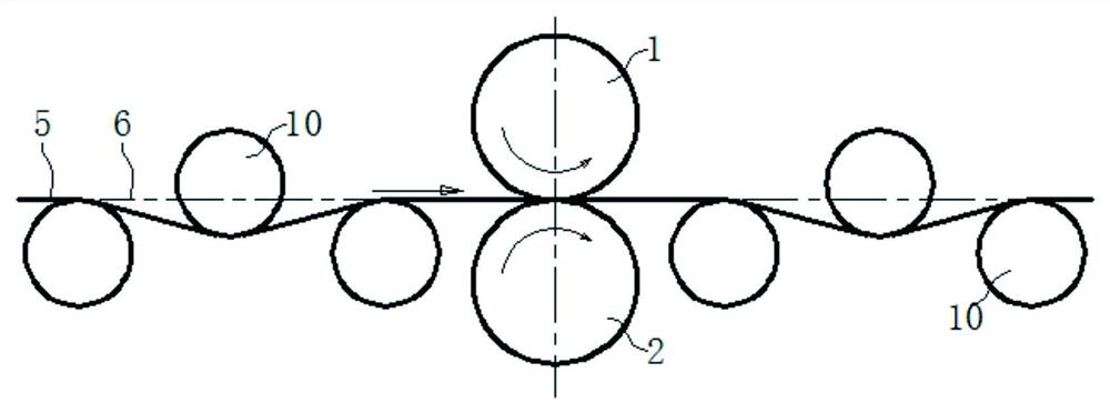
[0049] Such as Figure 5 As shown, a flattening roller 3 and an oil squeezing roller 4 are arranged on the entrance side of the roll gap, the roll diameter of the flattening roller 3 near the roll gap is 60mm, and the roll diameter of the oil squeezing roller 4 away from the roll gap is 30mm, the roll diameter of the flattening roll 3 is 2 times of the roll diameter of the squeeze roll 4. The roll surface of the flattening roll 3 is lower than the rolling center line 6, and the stri...

Embodiment 2

[0064] Such as Figure 13 As shown, the difference between this embodiment and Embodiment 1 is that the strip foil 5 enters the roll gap horizontally along the rolling center line 6, and a flattening roll 3 and an oil squeezing roll 4 are arranged on the exit side of the roll gap. The roll surface of the flattening roll 3 is higher than the rolling center line 6 . The flattening roller 3 post-stretches the strip foil 5 so that the strip foil 5 forms an exit-side cladding arc on the roll surface of the upper working roll 1, and the cladding angle of the exit-side cladding arc is β, and β is also 30°. Due to the existence of the wrapping arc on the exit side, the upper work roll 1 backs up the strip foil 5, and the tension is evenly distributed on the cross section of the wrapping arc on the exit side. The principle is as follows:

[0065] Such as Figure 14 As shown, the strip foil 5 flowing out from the roll gap is wrapped on the upper work roll 1 to form an outlet-side wrap...

Embodiment 3

[0069] This embodiment can be regarded as a combination of Embodiment 1 and Embodiment 2, such as Figure 15 As shown, the strip foil 5 forms an entry-side cladding arc with the lower work roll 2 on the entrance side of the roll gap, and the cladding angle α of the entrance-side cladding arc is 30°; the strip foil 5 works on the exit side and the upper work roll of the roll gap The roll 1 forms an exit-side cladding arc, and the cladding angle β of the exit-side cladding arc is also 30°. Due to the existence of the entrance-side cladding arc and the exit-side cladding arc, the lower work roll 2 and the upper work roll 1 respectively produce back support for the strip foil 5 .

[0070] The function and influence of the cladding arc on the entrance side in rolling has been explained in Example 1, and the function and influence of the cladding arc on the exit side in rolling has been explained in Example 2, so it will not be repeated here. It is worth noting that if Figure 16 ...


PUM

PropertyMeasurementUnit
diameteraaaaaaaaaa

Abstract

Wide strip foil rolling equipment comprises a rolling mill, a front adjusting roller set and a rear adjusting roller set. In a pair of working rollers of the rolling mill, the roller diameter of one working roller is larger than that of the other working roller. In the front adjusting roller set or the rear adjusting roller set, the roller diameter of an adjusting roller close to the rolling mill is larger than the roller diameter of the other adjusting rollers, and by adjusting the height of the adjusting roller with the larger roller diameter, strip foil is wrapped on the roller surface of one working roller to form a wrapping arc. According to the wide strip foil rolling equipment, the rolling mill with the working rollers with unequal diameters is adopted to roll the strip foil, and the front tension is uniformly distributed on the cross section of the wrapping arc on the inlet side through the wrapping arc. By means of the wide strip foil rolling equipment, thinning of the strip foil is facilitated, obtaining of a good plate shape is facilitated, uniform rolling of the strip foil is achieved, the bottleneck restricting development of the strip foil towards the wider, thinner and more ideal plate shape is broken through, and the technical problems in the industry are solved. In addition, the adjusting rollers with unequal diameters are favorable for eliminating the original defects of residual oil and strip foil.

Description

technical field [0001] The invention relates to the technical field of rolling, in particular to a rolling mill for rolling high-precision wide-width metal strips and foils. Background technique [0002] With the advancement of the technology industry, the market demand for high-precision wide-width thin strips and foils (hereinafter referred to as strips and foils) is becoming more and more urgent. Under the current technical background, the rolling technology for wide-width and thick strips has basically matured, but there are still many technical obstacles in the rolling technology of high-precision wide-width strip foil. For thicker strips, even if there are shape defects after rolling, the shape can still be corrected by tension leveling or other flattening means. For strip foils, especially thin foils, due to the lack of follow-up The means of shape correction can only be controlled by rolling. Especially for strips and foils with high deformation resistance such as ...

Claims


Application Information

Patent Timeline
Patent Type & Authority Applications(China)
IPC IPC(8): B21B1/40B21B39/16B21B37/68B21B45/02B21B37/28B21B37/48B21B27/02B21B13/02
CPCB21B1/40B21B39/16B21B37/68B21B45/0284B21B37/28B21B37/48B21B27/021B21B13/023
Inventor 刘洪勤马力徐继玲李毅
Owner SHANGHAI WUXING COPPER CO LTD
Why Eureka
Try Eureka