Synchronous phase shifting interference detection device based on orthogonal double grating and detection method

A technology of interference detection and synchronous phase shifting, which is applied to measurement devices, optical devices, instruments, etc., can solve the problems of low utilization rate of light energy and CCD effective area, and improve the effective area utilization rate. The method is simple and easy to implement. The effect of improving measurement accuracy

Inactive Publication Date: 2013-02-06
HARBIN ENG UNIV
View PDF4 Cites 15 Cited by
  • Summary
  • Abstract
  • Description
  • Claims
  • Application Information

AI Technical Summary

Benefits of technology

This patented technique uses both techniques for separating light into different colors (light) based on their wavelengths or other properties like refractive index difference between them. By combining these two technologies together, this process provides better results than just simply dividing up an entire scene onto multiple sensors that measure it separately. Additionally, by taking advantage of the strength of each component's ability to transmit signals faster over longer distances compared to traditional methods, the system becomes more efficient at measuring highly precise objects quickly without having to adjust its positioning frequently. Overall, this new approach simplifies the way we operate and reduces costs associated with current systems.

Problems solved by technology

Technological Problem addressed in this patents relates to improving the efficiency of achieving accurate measurements when performing simultaneously rotational and translational movements between different parts of space due to their relative movement speed. Existing methods have limitations that limit its effectiveness in accurately tracking fast motion phenomena like motions caused by external forces.

Method used


Image

  • Synchronous phase shifting interference detection device based on orthogonal double grating and detection method
  • Synchronous phase shifting interference detection device based on orthogonal double grating and detection method
  • Synchronous phase shifting interference detection device based on orthogonal double grating and detection method

Examples


specific Embodiment approach 1

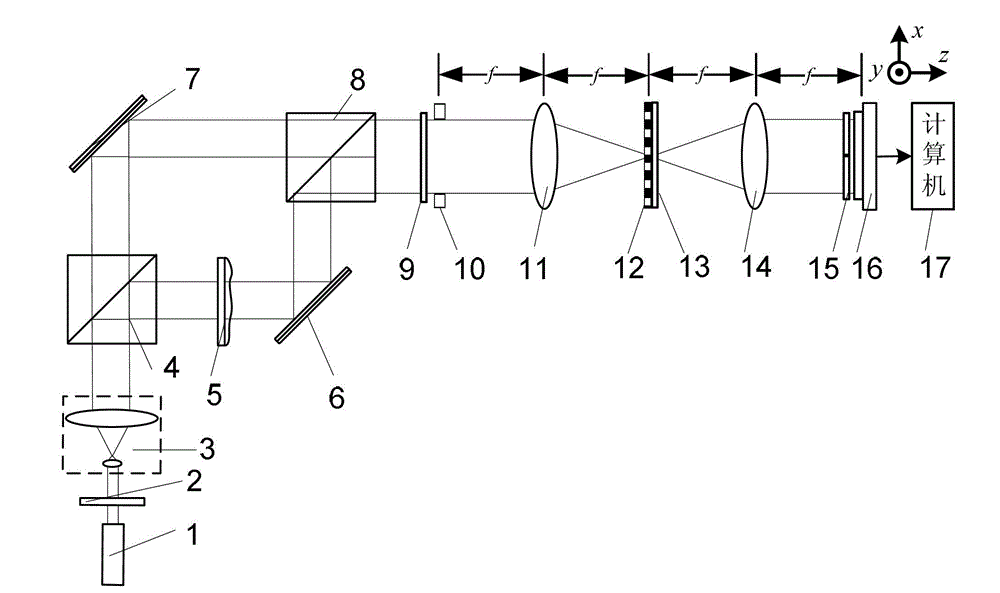
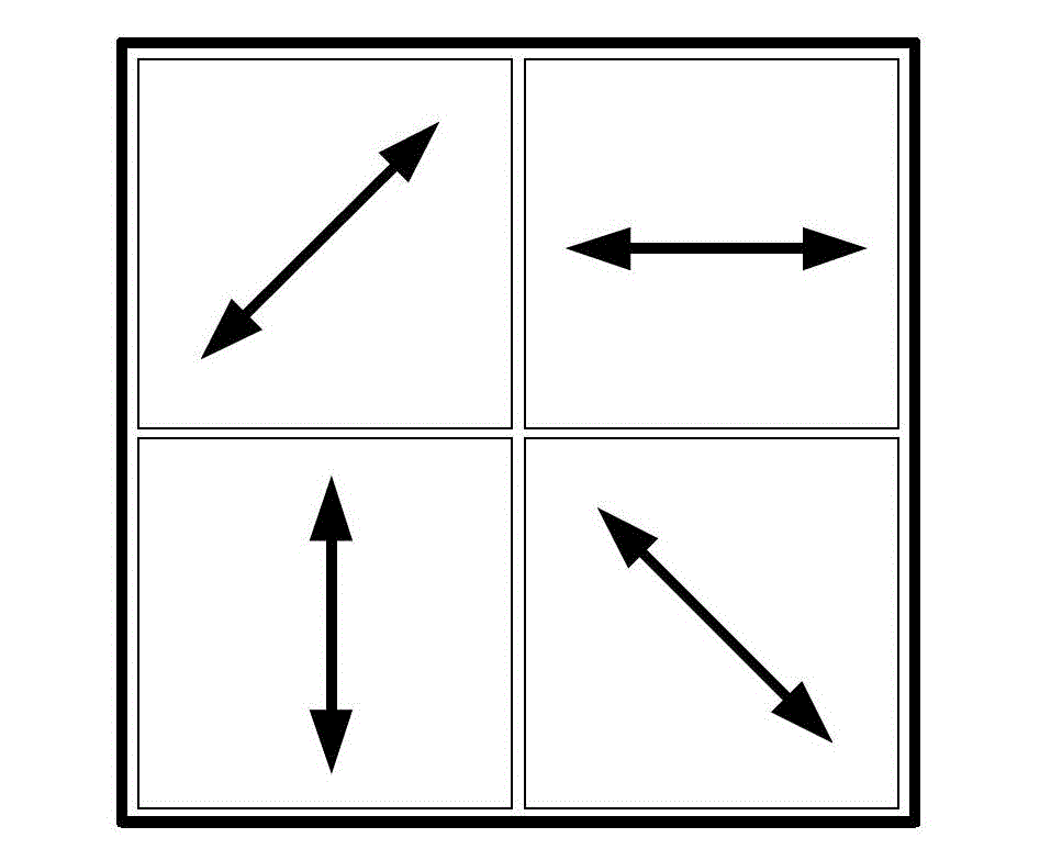
[0034] Specific implementation mode one: the following combination Figure 1 to Figure 4 Describe this embodiment, the synchronous phase-shifting interference detection device based on orthogonal double grating described in this embodiment, it comprises light source 1, it also comprises polarizer 2, collimation beam expander system 3, first polarizing beam-splitting prism 4, waiting Measuring object 5, first reflector 6, second reflector 7, second polarization beam splitter prism 8, λ / 4 wave plate 9, rectangular window 10, first Fourier lens 11, one-dimensional periodic amplitude grating 12, one Dimensional periodic phase grating 13, second Fourier lens 14, four-quadrant polarizer group 15, image sensor 16 and computer 17, wherein λ is the light wavelength of the light beam emitted by light source 1,

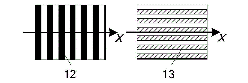
[0035] The one-dimensional period amplitude grating 12 and the one-dimensional period phase grating 13 form a double grating, and the one-dimensional period amplitude grating 12...

specific Embodiment approach 2

[0046] Embodiment 2: This embodiment is a further description of Embodiment 1. The one-dimensional periodic amplitude grating 12 is a binary one-dimensional periodic amplitude grating, a sine one-dimensional periodic amplitude grating or a cosine one-dimensional periodic amplitude grating.

specific Embodiment approach 3

[0047] Embodiment 3: This embodiment is a further description of Embodiment 2. The one-dimensional periodic phase grating 13 is a binary grating whose phases are 0 and π.


PUM


Abstract

The invention discloses a synchronous phase shifting interference detection device based on orthogonal double grating and a detection method. The synchronous phase shifting interference detection device belongs to the field of optical phase shifting interference detection. The problem that the conventional synchronous phase shifting method has low use ratios of luminous energy and a CCD (charge coupled device) effective area can be solved. According to the synchronous phase shifting interference detection device, a double-grating light split technology and a polarization modulation technology are combined, and linear polarization parallel light carried out collimation light expansion is divided into an object light beam and a reference light beam of which polarization directions are mutually vertical after passing through a first polarization light splitting prism; an object to be detected and a first reflecting mirror are arranged on a reflection direction of the first polarization light splitting prism; a second reflecting mirror is arranged on a transmission direction of the first polarization light splitting prism; in use and operation processes, a light path does not need to be changed, and no optical devices need to be moved; and four interference patterns can be obtained by one-time exposure collection so as to achieve a purpose of object phase recovery. The synchronous phase shifting interference detection device is suitable for measuring an optical surface, deformation and thickness and the like.

Description


Claims


Application Information

Patent Timeline
Owner HARBIN ENG UNIV
Why Eureka
Try Eureka