Mine mining fracture evolution and distribution monitoring device and method

A fissure evolution and monitoring device technology, applied in the field of mine pressure and safety, can solve the problems of not being able to reflect the time and space evolution of coal and rock mass mining fissures in time, and unable to meet the actual needs of mines, so as to reduce the detection workload, The effect of high degree of automation and simple method

Active Publication Date: 2011-12-28
XUZHOU FUAN TECH
View PDF3 Cites 51 Cited by
  • Summary
  • Abstract
  • Description
  • Claims
  • Application Information

AI Technical Summary

Problems solved by technology

It should be pointed out that the above methods are all carried out in a single borehole, because the deformation and damage of the overburden and floor strata caused by coal seam mining are dynamic and temporal, that is, the fracture network changes with time as the mining activities proceed. and spatial dynamic changes, so the detection effect through a single borehole can only reflect the development of cracks in the local area of ​​the hole wall, and the detection results only reflect the cracks during the drilling period, which is a static observation
In the case of a limited number of drill holes, the detection results cannot fully reflect the occurrence and distribution of coal and rock mass fissures in the comparative space, let alone reflect the evolution of coal and rock mass mining cracks over time and space in a timely manner, which cannot meet the needs of mines. the actual needs of

Method used


Image

  • Mine mining fracture evolution and distribution monitoring device and method
  • Mine mining fracture evolution and distribution monitoring device and method
  • Mine mining fracture evolution and distribution monitoring device and method

Examples


Embodiment Construction

[0022] An embodiment of the present invention is described below in conjunction with accompanying drawing:

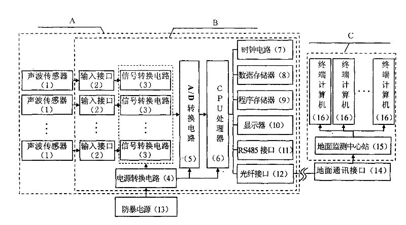
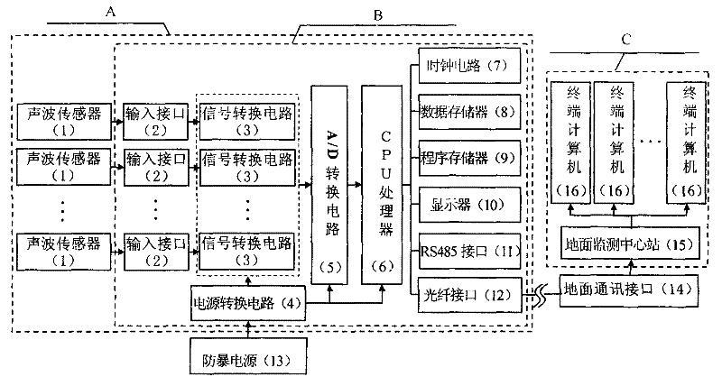
[0023] figure 1As shown, the mining fracture evolution and distribution monitoring device of the present invention is mainly composed of four parts: an explosion-proof acoustic wave monitor A, an explosion-proof power supply 13, a ground communication interface 14, and a ground monitoring and analysis center C. Explosion-proof sound wave monitor A is mainly composed of sound wave sensor 1, input interface 2, signal conversion circuit 3, power conversion circuit 4, A / D conversion circuit 5, CPU processor 6, clock circuit 7, data memory 8, program memory 9, display 10. Composed of RS485 interface 11 and optical fiber interface 12. Wherein the acoustic wave sensor 1 is an acoustic emission sensor or a micro-vibration sensor; there are at least four acoustic wave sensors; the A / D conversion module of the A / D conversion circuit 5 selects the ADS7852 chip; the CPU processor ...


PUM


Abstract

The invention discloses a device and method for monitoring the evolution and distribution of a mining-induced fracture. Generation, evolution and distribution of the mining-induced fracture are monitored through a method of monitoring acoustic wave or vibration generated in fracture of coal or rock. The device mainly comprises an anti-explosion acoustic wave monitor, an anti-explosion power source and a ground monitoring analysis center, wherein the anti-explosion acoustic wave monitor consists of a sonic sensor and a signal conversion and data acquisition instrument; the sonic sensor is arranged on a roadway base plate, an anchor rod tail end or a drill hole; and an acoustic wave or vibration signal monitored by the sonic sensor is collected and processed by the signal conversion and data collection instrument, and is transmitted to the ground monitoring analysis center through an optical fiber port to be subjected to processing, positioning and quantitative analyzing and be labeled on a plane, a cross section or a space diagram according to the position and size, so as to show the position and size of the fracture. The device and method provided by the invention has the beneficial effects of large monitoring range, a large amount of comprehensive monitoring information, high automation degree, strong instantaneity and capability of being applied to monitoring and forecastingthe coal rock dynamic disasters, such as rock burst, and outburst and water burst of coal and gas and the like.

Description

technical field [0001] The invention relates to a monitoring device and method, in particular to a monitoring device and method for monitoring the evolution and distribution of mining cracks by monitoring sound waves or vibrations generated by coal rock rupture, and belongs to the technical field of mine pressure and safety. It can also be applied to the monitoring and forecasting of coal and rock dynamic disasters such as rockburst (rock burst), coal and gas outburst, and water inrush. Background technique [0002] The mine rock mass is in the state of original stress balance under natural conditions. The excavation activities in underground mines cause the redistribution of stress field and the activities of surrounding rocks, including the deformation of surrounding rocks and the generation of mining cracks. The generation of mining fissures is the fracture behavior that occurs after the stress of the surrounding rock exceeds the ultimate stress that it can bear. In the...

Claims


Application Information

Patent Timeline
Patent Type & Authority Applications(China)
IPC IPC(8): G01V1/00G01V1/22G08C23/06
Inventor 王恩元许福乐王喜元
Owner XUZHOU FUAN TECH
Why Eureka
Try Eureka