Power supply power device radiation structure

A heat dissipation structure and power supply technology, applied in the direction of cooling/ventilation/heating transformation, etc., can solve problems such as difficult to meet the vibration conditions and damage of automobiles, and achieve the effect of improving the anti-seismic effect and improving the heat dissipation efficiency

Inactive Publication Date: 2013-02-06
SHENZHEN MEGMEET ELECTRICAL CO LTD
View PDF9 Cites 3 Cited by
  • Summary
  • Abstract
  • Description
  • Claims
  • Application Information

AI Technical Summary

Problems solved by technology

The installation method of the above power devices is difficult to

Method used


Image

  • Power supply power device radiation structure
  • Power supply power device radiation structure
  • Power supply power device radiation structure

Examples


Example Embodiment

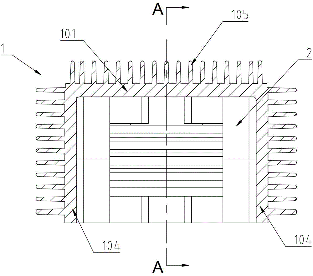
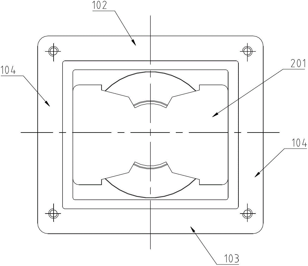
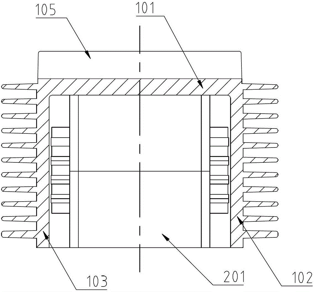
[0028] exist Figure 1 to Figure 3 The heat dissipation structure of the power supply device in the illustrated embodiment 1 of the present invention includes a radiator 1 and a transformer 2. The radiator 1 includes a top plate 101, a front plate 102, a rear plate 103 and two side plates 104, and the top plate 101 and two The side plate 104 forms a U-shaped structure; the front plate 102 and the rear plate 103 are respectively connected with the top plate 101 and the side plate 104 to form a box-shaped structure with an open lower end.

[0029] The open slot formed by the top plate 101 , the front plate 102 , the rear plate 103 and the two side plates 104 is the installation slot of the transformer 2 ; the transformer 2 is installed in the open slot.

[0030] The magnetic core 201 of the transformer 2 includes a top surface and two side surfaces. The top surface and the two side surfaces of the magnetic core 201 are respectively attached to the top plate 101 and the two side ...


PUM


Abstract

The invention discloses a power supply power device radiation structure which comprises a radiator and at least one power magnetic device. The radiator comprises a top plate and two side plates; the top plate and the two side plates form a U-shaped structure; the open slot formed by the top plate and the side plates is a power magnetic device installation slot; the power magnetic device is arranged in the open slot and radiates through the top plate and the side plates. Because the single-side radiation of the power magnetic device is changed into multiple-side radiation, the radiating efficiency of the power magnetic device is improved, and because the power magnetic device is arranged in the open slot of the radiator, the anti-seismic effect of the power magnetic device can be improved. The power supply power device radiation structure is particularly suitable for the automobile power supply.

Description

[technical field] [0001] The invention relates to a heat dissipation structure of a device, in particular to a heat dissipation structure of a power device. [Background technique] [0002] The small power devices in the traditional power supply series flat package, such as semiconductor power devices, power resistors, etc., and power magnetic devices, such as transformers, inductors, etc., use the main heat dissipation surface of these power devices to dissipate heat on one side, and use screws to pass through the power The fixing holes on the device, or the use of pressure strips to press the main heat dissipation surface of the power device and the heat dissipation surface of the radiator to conduct heat conduction. The disadvantage of this heat dissipation method is that the installation process is complicated, there are many auxiliary materials such as beading and screws, and the cost is relatively high; the power device dissipates heat on one side, and the heat dissipat...

Claims


Application Information

Patent Timeline
IPC IPC(8): H05K7/20
Inventor 吴坤
Owner SHENZHEN MEGMEET ELECTRICAL CO LTD
Why Eureka
Try Eureka