Method and arrangement in a wireless network for determining an uplink received power target value

A receiving power and wireless network technology, applied in the field of wireless network, can solve the problems of downlink bit rate degradation, waste of good SIR, etc., and achieve the effect of improved performance and high capacity

Active Publication Date: 2013-02-06
TELEFON AB LM ERICSSON (PUBL)
View PDF2 Cites 0 Cited by
  • Summary
  • Abstract
  • Description
  • Claims
  • Application Information

AI Technical Summary

Problems solved by technology

However, there is a waste of good SIR if the noise level is increased in smaller cells
Wi

Method used


Image

  • Method and arrangement in a wireless network for determining an uplink received power target value
  • Method and arrangement in a wireless network for determining an uplink received power target value
  • Method and arrangement in a wireless network for determining an uplink received power target value

Examples


Example Embodiment

[0037] The present invention is defined as a method and device in a wireless network node, and the method and device can be implemented in the embodiments described below. However, the present invention can be implemented in many different forms, and the present invention is not to be regarded as limited to the embodiments set forth herein; rather, these embodiments are provided so that this disclosure will be thorough and complete and will be useful to those skilled in the art Convey the scope of the invention.

[0038] Although from the following detailed description considered in conjunction with the accompanying drawings, other objects and features of the present invention may become apparent. However, it should be understood that the design of the drawings is only for illustrative purposes and not as a definition of the limits of the present invention. For the definition of the limits of the present invention, reference should be made to the appended claims. It is also to b...


PUM


Abstract

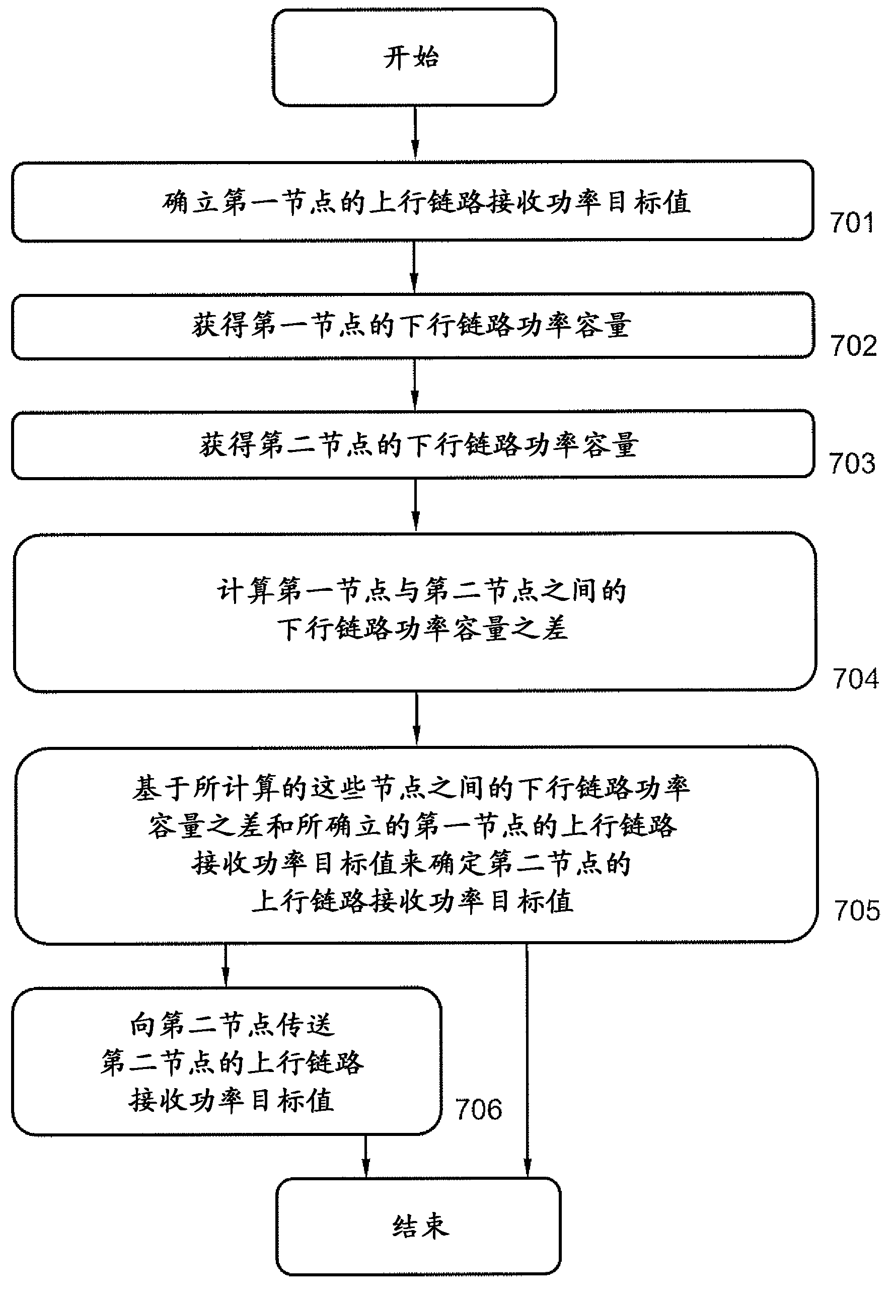
Method and arrangement in a wireless network, comprising a first node and an adjacent second node, for determining an uplink received power target value of the second node, to be used by a user equipment which is to be served by the second node, the downlink power capacity of the first node exceeds the downlink power capacity of the second node. The method comprises establishing the uplink received power target value of the first node, obtaining the downlink power capacity of the first node, obtaining the downlink power capacity of the second node, calculating the difference in downlink power capacity between the first node and the second node, and determining the uplink received power target value of the second node, based on the calculated difference in downlink power capacity between the nodes and the established uplink received power target value of the first node.

Description

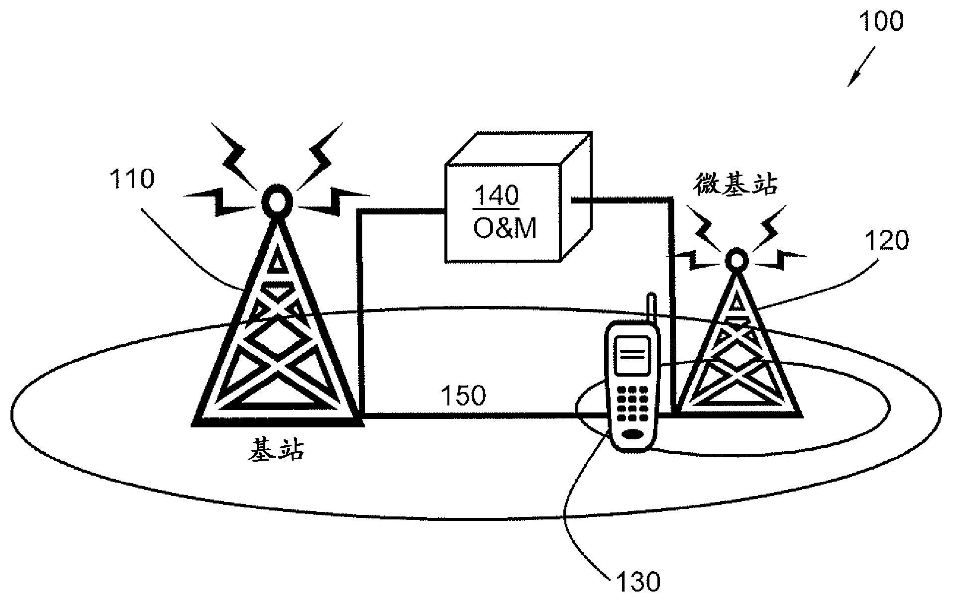
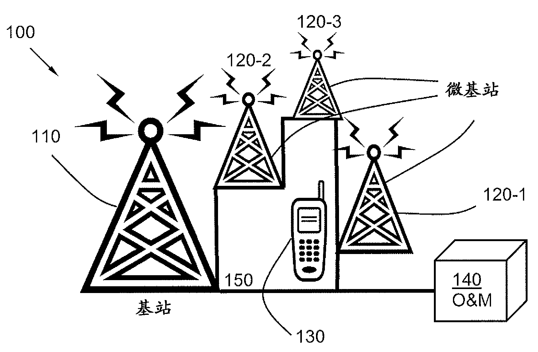
technical field [0001] The present invention relates to methods and devices in wireless networks. In particular, it relates to a mechanism for determining an uplink receive power target value of a second node to be used by a user equipment to be served by the second node. Background technique [0002] In mixed heterogeneous networks with different cell sizes, usually different downlink power levels are used, which present different cell sizes. For example, there may be a 1OdB-2OdB difference between a macro site and a micro site. There are several different nodes that are expected to be deployed with different downlink power levels, such as macro base stations, micro base stations, pico base stations, femto base stations, repeaters and repeaters. [0003] A macro base station may be referred to as a regular base station that uses a dedicated backhaul and is open to public access. Typical transmit power may eg be ~43dBm and antenna gain may be ~12-15dBi. [0004] A pico b...

Claims


Application Information

Patent Timeline
IPC IPC(8): H04W52/04
CPCH04W52/146H04W52/244H04W52/10H04W52/12
Inventor A.富鲁斯凯尔K.希尔图宁P.莫贝里A.西蒙松
Owner TELEFON AB LM ERICSSON (PUBL)
Why Eureka
Try Eureka