Whole width recognition cutting machine and whole width recognition cutting method

A cutting machine and cutting head technology, applied in welding equipment, laser welding equipment, metal processing equipment, etc., can solve the problems of low work efficiency and long identification time of laser identification cutting machine, and achieve the goal of improving production efficiency and shortening identification time. Effect

Active Publication Date: 2016-03-02
TONGFU MFG
View PDF4 Cites 0 Cited by
  • Summary
  • Abstract
  • Description
  • Claims
  • Application Information

AI Technical Summary

Problems solved by technology

[0003] The present invention mainly aims at the problems of long recognition time and low work efficiency of the current laser recognition cutting machine, and provides a whole-width recognition cutting machine, including an imager, a workbench and a cutting head assembly, a rail installed in the center of the top of the workbench, a processing The imager is a full-frame imager, which is installed in the track and can move up and down along the track. The processor is respectively connected with the imager and the cutting head assembly through a data transmission device

Method used


Image

  • Whole width recognition cutting machine and whole width recognition cutting method
  • Whole width recognition cutting machine and whole width recognition cutting method

Examples


Embodiment 1

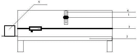
[0013] Such as figure 1 As shown, the full-width recognition cutting machine includes a full-width imager 1, a workbench 2, a cutting head assembly 3, a computer 5, and a track 4 installed in the center of the top of the workbench. The whole-width imager 1 is installed in the track 4, and can be The track 4 moves up and down, and the computer 5 is respectively connected with the imager 1 and the cutting head assembly 3 through a data transmission device. Because the main innovation in the present invention lies in the identification technology, so the specific components of the cutting head assembly 3 will not be described in detail. The cutting path in is finished cutting. When cutting the product, first lay the web with several cutting units on the workbench 2, turn on the power, the entire imager 1 moves in the track 4, and continuously adjusts according to the imaging accuracy and imaging definition during the movement The height of itself, when it is selected to a suita...

Embodiment 2

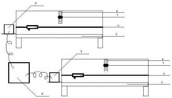
[0015] Such as figure 1 As shown, the full-width recognition cutting machine includes a full-width imager 1, a workbench 2, a cutting head assembly 3, a computer 5, and a track 4 installed in the center of the top of the workbench. The whole-width imager 1 is installed in the track 4, and can be The track 4 moves up and down, and the computer 5 is respectively connected with the imager 1 and the cutting head assembly 3 through a data transmission device. Because the main innovation in the present invention lies in the identification technology, so the specific components of the cutting head assembly 3 will not be described in detail. The cutting path in is finished cutting. When cutting the product, first lay the web with several cutting units on the workbench 2, turn on the power, the entire imager 1 moves in the track 4, and continuously adjusts according to the imaging accuracy and imaging definition during the movement The height of itself, when it is selected to a suita...


PUM


Abstract

The invention relates to a whole breadth identifying and cutting machine and methods for identifying and cutting the whole breadth by using the whole breadth identifying and cutting machine and aims to solve the problems that the identification time is long, and the conventional laser identifying and cutting machine is low in working efficiency. The whole breadth identifying and cutting machine comprises an imaging device, a working table, a cutting head component, a rail arranged in the center of the top of the working table and a processor, wherein the imaging device is a whole-breadth imaging device and arranged in the rail and can do up-and-down motion along the rail; and the processor is respectively connected with the imaging device and the cutting head component through a data transmission device. By the whole breadth identifying and cutting machine, effects of identifying and cutting the whole breadth in a unified mode are achieved, so that the identification time is greatly shortened, and the production efficiency of a laser cutting machine is effectively improved.

Description

technical field [0001] The invention relates to a processing device and a corresponding processing method thereof, in particular to a laser cutting machine and a cutting method using the laser cutting machine for processing. Background technique [0002] In the current prior art, the recognition cutting machine mainly includes a recognition head, a cutting head, a working table and other related equipment components. The recognition head and the cutting head are fixed together, usually the format to be cut is pre-laid on the worktable, the recognition head collects and compares the recognition patterns on the pattern, and further according to the cutting pattern preset in the numerical control device Compare and then cut by the cutting head. This process usually takes 30s or more. In other words, it takes such a time to recognize each graphic in a format, so the work efficiency of the recognition cutting machine is much lower than that of other laser cutting machines. Co...

Claims


Application Information

Patent Timeline
Patent Type & Authority Patents(China)
IPC IPC(8): B23K26/38B23K26/042B23K26/082B23K26/08
Inventor 周大成
Owner TONGFU MFG
Why Eureka
Try Eureka