
Paper tube forming device

A forming device and paper tube technology, applied in the direction of paperboard winding articles, etc., can solve the problems of paper tube inner wall damage, paper tube forming shaft wear, raw material waste, etc., to improve the probability of damage, prolong the service life, and improve production efficiency Effect

Active Publication Date: 2013-02-13
GOLD HONG YE PAPER
View PDF6 Cites 3 Cited by
  • Summary
  • Abstract
  • Description
  • Claims
  • Application Information

AI Technical Summary

Problems solved by technology

[0004] However, in the existing paper tube production process, since the paper tube will continue to slide forward along the axis of the paper tube forming shaft after forming, as the length of the paper tube continues to grow, the friction between the paper tube and the paper tube forming shaft will The force also gradually increases with the
The increasing friction will not only make it difficult for the paper tube to slide on the paper tube forming shaft, which will cause damage to the inner wall of the paper tube and affect the quality of the paper tube, but also in the continuous production process, the increasing friction will also make the paper tube form Severe shaft wear, resulting in low production efficiency and waste of raw materials

Method used


Image

  • Paper tube forming device
  • Paper tube forming device

Examples


Embodiment Construction

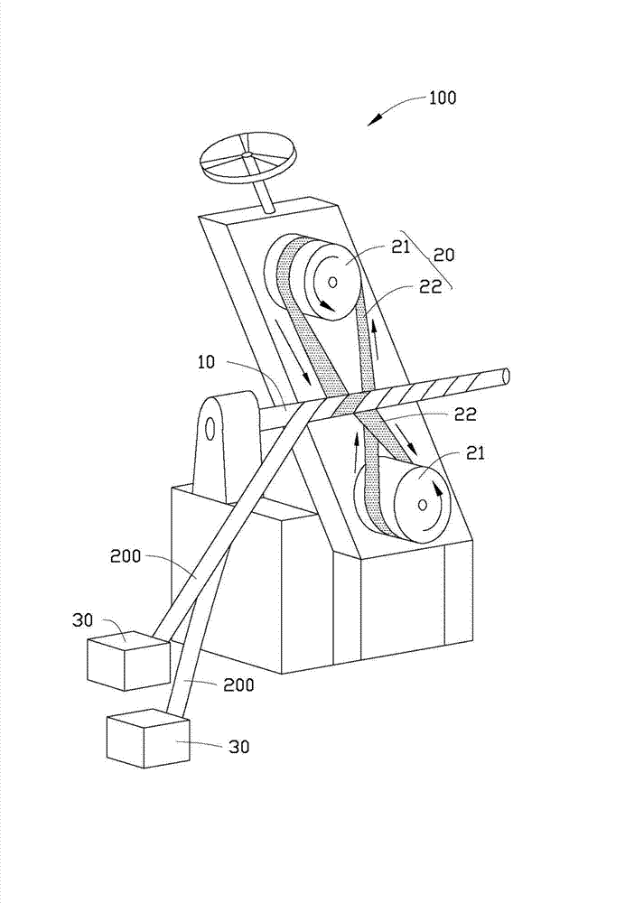
[0014] See figure 1 and figure 2 As shown, the paper tube forming device 100 provided by the embodiment of the present invention includes a paper tube forming shaft 10, a power device 20, and a paper tape conveying device 30, wherein the paper tape conveying device 30 is used to provide a paper tape 200, so The power device 20 is used to drive the paper tape 200 to rotate and wind on the paper tube forming shaft 10 to form a paper tube, and at the same time drive the paper tube to slide along the axis of the paper tube forming shaft 10 .

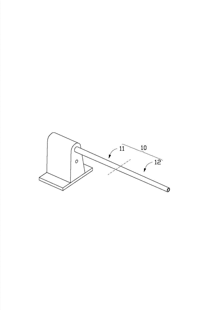
[0015] The paper tube forming shaft 10 includes a paper input forming section 11 and a paper output section 12 . In this embodiment, the paper input forming section 11 and the paper output section 12 are integrally structured. Of course, it can be understood that the paper-entry forming section 11 and the paper-out section 12 can also be detachably connected to each other by screw threads or the like.

[0016] In the present invention, t...


PUM


Abstract

The invention relates to a paper tube forming device which comprises a paper tube forming shaft, a paper tape conveying device and a power device; the paper tape conveying device is used for supplying paper tapes to the paper tube forming shaft; the paper tube forming shaft comprises an inlet paper forming section and an outlet paper section; the power device is used for driving the paper tapes to be rotated and wound on the paper tube forming shaft so as to form paper tubes and simultaneously driving the paper tubes to slide from the inlet paper forming section to the outlet paper section along the axial line of the paper tube forming shaft; and the diameter of the paper tube forming shaft decreases gradually from the inlet paper forming section to the outlet paper section. Compared with the prior art, the paper tube forming device provided by the invention can effectively reduce the probability of damage caused by friction force of the inner walls of the paper tubes during the winding process and prolongs the service life of the paper tube forming shaft at the same time.

Description

technical field [0001] The invention relates to a paper tube forming device. Background technique [0002] Paper tubes are widely used in industrial production in various industries, such as papermaking, textile, chemical fiber and other industries, and are the basic carriers for winding or winding paper rolls, cloth, films, yarns, etc. At present, the production process of the paper tube is generally driven by a motor to rotate a forming shaft, and the multi-layer paper tube paper is glued and rotated by the forming shaft to be wound into a cylindrical paper tube. [0003] The commonly used paper tube forming shaft generally includes a paper feeding section and a paper output section. The paper tape enters from the paper feeding section at a certain inclination angle and begins to spirally wind to form a paper tube. The paper forming section slides along the axis of the paper tube forming shaft to the paper outlet section and finally slides out of the paper tube forming sh...

Claims


Application Information

Patent Timeline
Patent Type & Authority Applications(China)
IPC IPC(8): B31C3/00
Inventor 曾学强朱记莲
Owner GOLD HONG YE PAPER
Learn More