Fiber short cutter roller capable of adjusting cut-in angle of cutter in stepless mode

A stepless adjustment, knife roll technology, used in fiber cutting, fiber processing, textiles and papermaking, etc., to improve the chopped effect, reduce production costs, and prolong service life.

Inactive Publication Date: 2013-02-13
ZHEJIANG UNIV
View PDF10 Cites 10 Cited by
  • Summary
  • Abstract
  • Description
  • Claims
  • Application Information

AI Technical Summary

Problems solved by technology

[0003] In order to overcome the problems of the fiber chopping knife roll in the background technology, the object of t

Method used


Image

  • Fiber short cutter roller capable of adjusting cut-in angle of cutter in stepless mode
  • Fiber short cutter roller capable of adjusting cut-in angle of cutter in stepless mode
  • Fiber short cutter roller capable of adjusting cut-in angle of cutter in stepless mode

Examples


Embodiment Construction

[0015] The present invention will be further described below in conjunction with the accompanying drawings and embodiments.

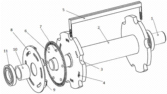
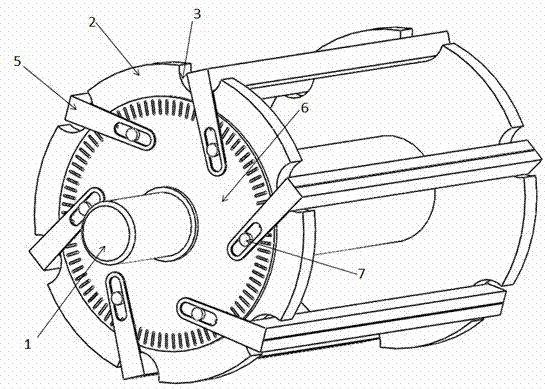
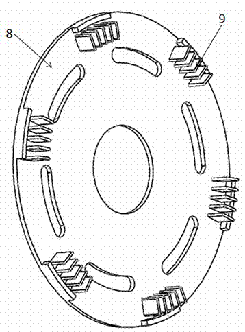
[0016] Such as figure 1 , figure 2 , image 3 , Figure 4 As shown, the present invention includes an I-shaped knife roller 2, six rotating knife grooves 5 with vertical lever arms at both ends of the same structure, two angle plates 6 with the same structure, two positioning plates 8 with the same structure and a ladder Shaft 1; the I-shaped knife roller 2 is installed in the middle of the stepped shaft 1, the inner hole of the I-shaped knife roller 2 is fixedly connected with the stepped shaft 1, and the two ends of the I-shaped knife roller 2 are respectively opened with etc. There are six arc-shaped grooves 3 distributed at intervals, and six sets of card slots 4 consisting of a plurality of elongated grooves are formed equidistantly on the side of the cylindrical surface at both ends of the I-shaped knife roller 2. Angle plate 6, positioning p...


PUM


Abstract

The invention discloses a fiber short cutter roller capable of adjusting a cut-in angle of the cutter in stepless mode. The fiber short cutter roller comprises an I-shaped cutter roller, two angle discs with the same structure, two positioning discs with the same structure and stair shafts, wherein the I-shaped cutter roller is installed in the middle of the stair shafts and fixedly connected with the stair shafts, and the angle discs, the positioning discs, sleeves and bearings are sequentially installed on the stair shafts outside two ends of the I-shaped cutter roller outwards. By means of the design of the angle discs and a rotary cutter groove, the cut-in angle of the cutter can be adjusted in stepless mode, and after the device is installed, the cut-in angles (ranging from 0 degree to 30 degrees) of all long blades can be adjusted by rotating the angle discs in one step, further the cut-in angles of all the long blades are ensured to be same, the problem that the existing short cutting devices cannot adjust the cut-in angles is solved, the short cutting effect is improved, service life of the cutter is prolonged, and production cost is reduced.

Description

technical field [0001] The invention relates to a fiber cutting device, in particular to a fiber chopped cutter roller capable of steplessly adjusting the cutting angle of the cutter. Background technique [0002] At present, although the chopping equipment used in the actual production of various fiber chopped strands has various structures such as pressure wheel type, groove wheel type, and groove plate type, their cutting forms are basically the same, that is, the cutting edge of the knife is parallel to the fiber filaments. The radial cut, that is, the cut angle is 0°. Existing studies have shown that when the cutting edge of the tool cuts in at a certain angle to the radial direction of the fiber filament, it can have a better chopping effect, and the cutting angle varies with the fiber to be cut. For example, Yuan Yigao, Zhu Shigen and others found in the research on the edge angle of the chemical fiber cutting knife that when cutting polyester semi-dull fiber, when t...

Claims


Application Information

Patent Timeline
IPC IPC(8): D01G1/00B26D1/36B26D7/26
Inventor 周继烈冯楚凡孙中浩
Owner ZHEJIANG UNIV
Why Eureka
Try Eureka