Coupling unit for connecting a drive with an output

A drive unit and coupling technology, applied in the direction of couplings, elastic couplings, mechanical equipment, etc., can solve the problem of reducing the angle compensation capability of couplings, limiting angular deviation and axial deviation, limiting rotational torque, etc. problem, to achieve the effect of compensating axial deviation

Inactive Publication Date: 2013-02-13
CENTA ANTRIEBE KIRSCHEY GMBH
View PDF6 Cites 5 Cited by
  • Summary
  • Abstract
  • Description
  • Claims
  • Application Information

AI Technical Summary

Problems solved by technology

[0007] Possible angular and axial misalignments of the two components are limited by the necessary application of distance-compensating rubber elements
In addition, the elastomer material also limits the maximum rotational torque to be transmitted
In order to increase the rotational moment load of the coupling, it is necessary to increase the structural shape of the coupling itself and increase the number of guide rods used, which correspondingly reduces the angle compensation capability of the coupling

Method used


Image

  • Coupling unit for connecting a drive with an output
  • Coupling unit for connecting a drive with an output
  • Coupling unit for connecting a drive with an output

Examples


Embodiment Construction

[0037] exist Figure 4 with Figure 5 , the coupling is indicated generally by the reference numeral 100 .

[0038] The coupling 100 includes two coupling units generally indicated by reference numeral 110 . The coupling units 110 are arranged axially one behind the other in the force flow direction KF and are coupled to one another via a shaft 114 . The force flow flows from a drive unit AN (not shown) to an output unit AB (also not shown). A structural element described hereinafter as drive unit side is generally arranged on the drive unit side relative to another structural element, and a structural element indicated hereinafter as driven unit side is generally arranged on the driven unit side relative to another structural element.

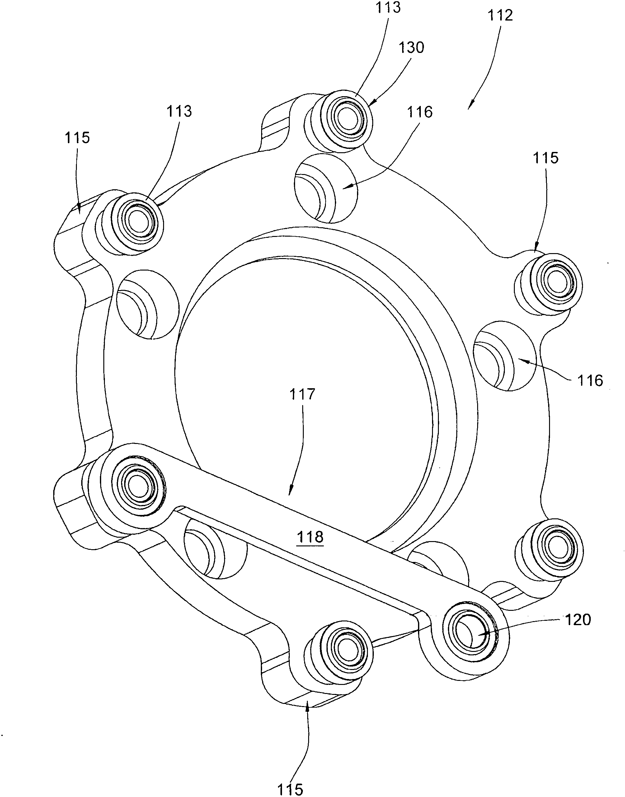
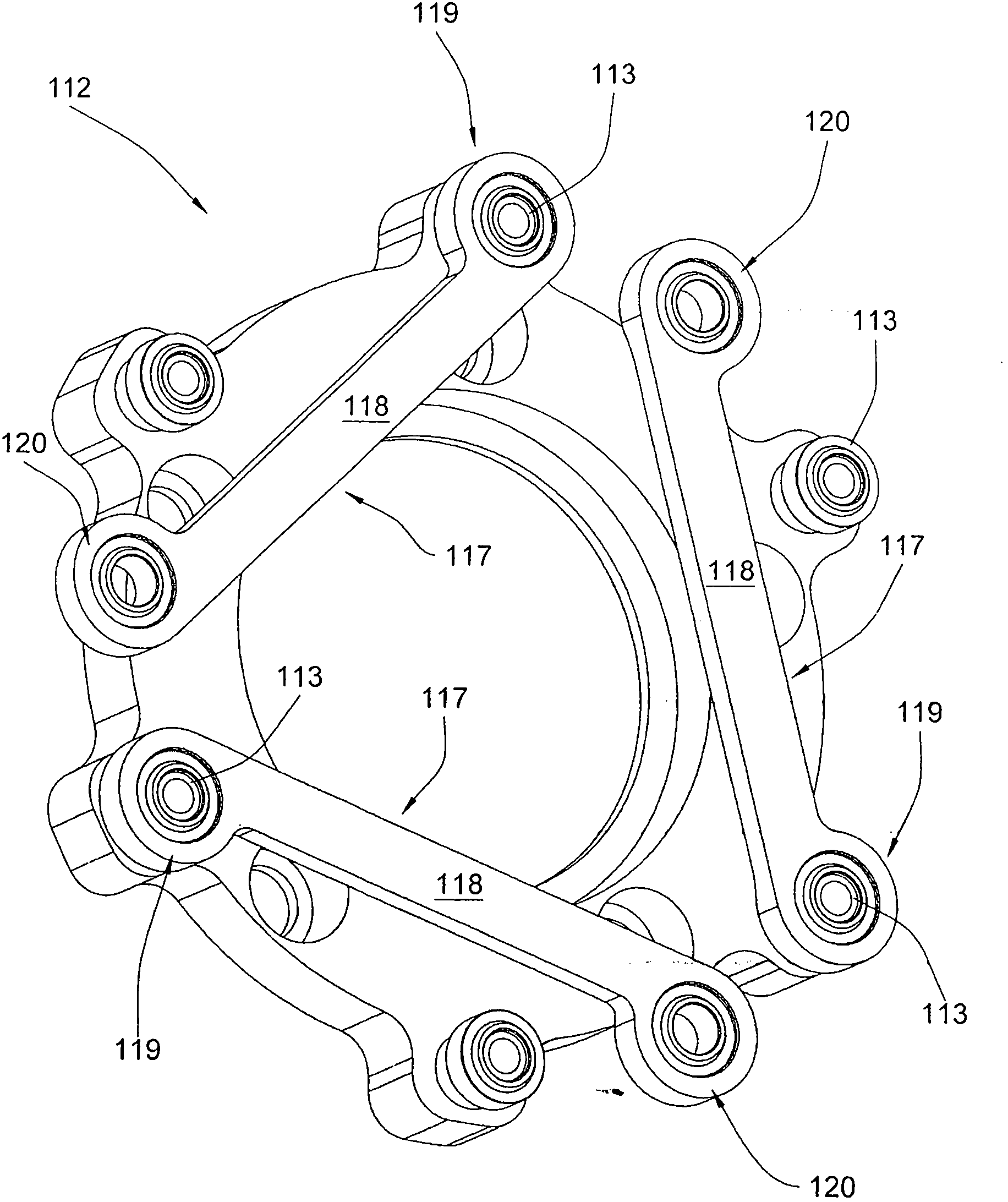
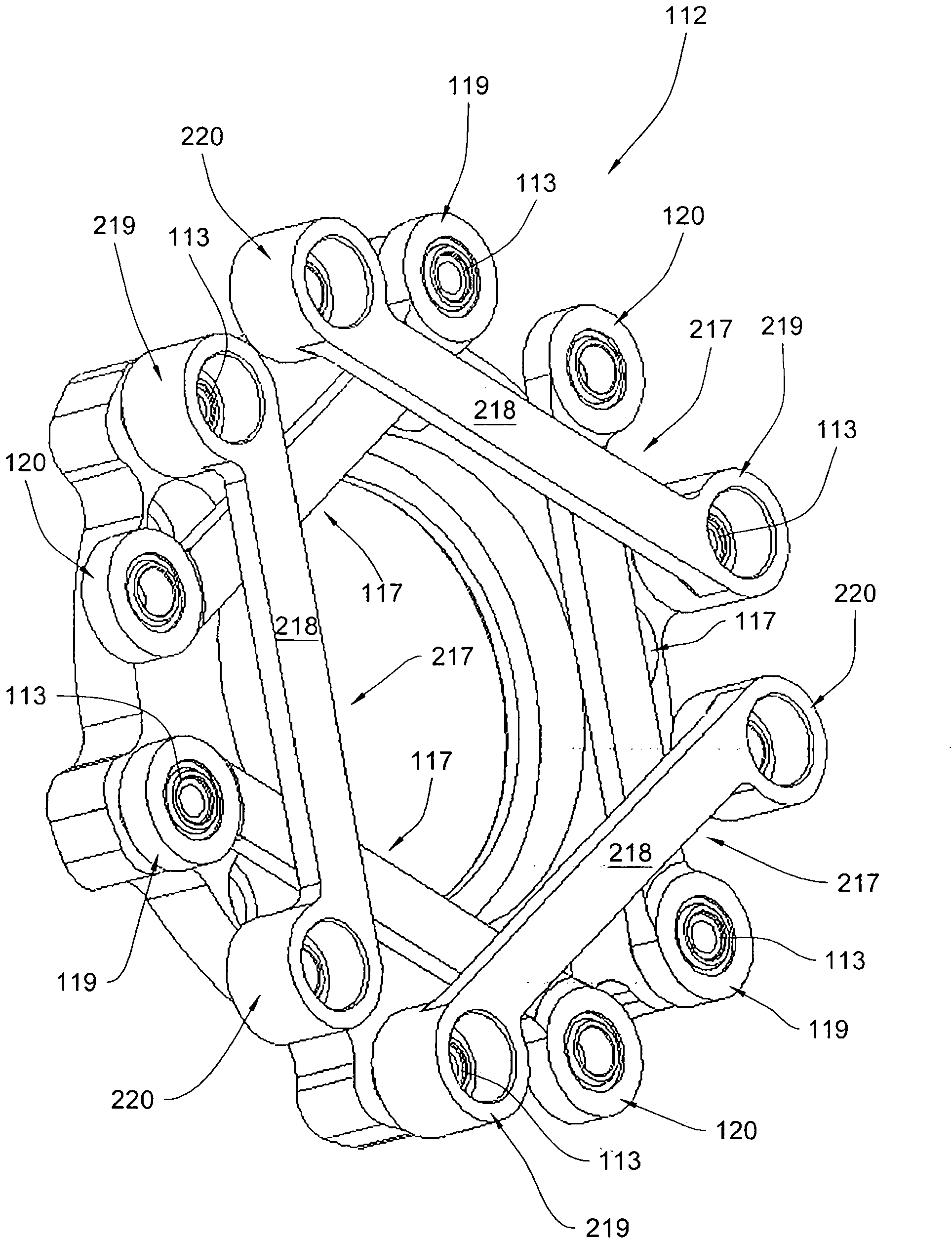
[0039] exist figure 1A drive-unit-side connecting device 112 is shown in , which is also referred to as a drive-unit-side flange 112 or a drive-unit-side flange ring 112 . The flange 112 is annular and is provided with star-ray-like proje...


PUM


Abstract

A coupling for connecting a drive to a load has an input connector that defines with a plurality of radially spaced input attachment points all lying on a common radial plane of a rotation axis and a similar output connector with a plurality of output attachment points. Connecting elements each have one end connected to a respective input attachment point and an opposite end connected to a respective output attachment point by a link joint. The radial spacing of the input attachment points from the input rotation axis and the radial spacing of the output attachment points from the output rotation axis are the same. The input attachment points and the output attachment points coupled to these input attachment points by a connecting element are angularly spaced relative to each other about the input rotation axis by 80 DEG to 100 DEG .

Description

technical field [0001] The invention relates to a coupling unit for connecting a driving unit and a driven unit, comprising: [0002] - connection means on the drive unit side, e.g. flanges, which have a drive unit-side axis of rotation and are provided with a plurality of drive unit-side fixing elements, which are all arranged in a common radial plane of the axis of rotation and are arranged on a common radius around the axis of rotation of the coupling on the drive unit side, [0003] - connection means on the driven unit side, such as flanges, which have a driven unit-side rotational axis and are provided with a plurality of driven unit-side fastening elements, which are all arranged on a common diameter of the rotational axis arranged in the plane and on a common radius around the axes of rotation of the coupling means on the driven unit side, and [0004] - connecting elements, such as guide rods or coupling rods, which are connected by means of a joint, in particular b...

Claims


Application Information

Patent Timeline
Patent Type & Authority Applications(China)
IPC IPC(8): F16D3/62
CPCF16D3/60
Inventor J·埃克斯纳D·埃克斯纳
Owner CENTA ANTRIEBE KIRSCHEY GMBH
Why Eureka
Try Eureka