Light emitting diode (LED) spherical lamp transmitting heat through liquid

An LED spherical lamp, liquid technology, applied in lighting and heating equipment, semiconductor devices of light-emitting elements, cooling/heating devices of lighting devices, etc. The heat dissipation structure is simple and compact, the production cost is reduced, and the heat dissipation effect is excellent.

Inactive Publication Date: 2014-08-20
浙江阳光照明灯具有限公司
View PDF9 Cites 0 Cited by
  • Summary
  • Abstract
  • Description
  • Claims
  • Application Information

AI Technical Summary

Problems solved by technology

However, in order to meet the demand for high luminous flux of general lighting, people carry out the research and development of high-power LED lamps of 9W and above. It is necessary to control the temperature of the LED pins below 80 degrees Celsius, and to obtain high luminous efficacy and long life. , which makes the heat dissipation design requirements of high-power LED lamps higher, and the surface area of ​​the heat sink has to be increased to dissipate a large amount of heat. Such a heat sink has a heavy mass, a large amount of metal, a large volume, complex manufacturing, and high cost.
[0004] At present, various heat dissipation technologies, such as heat pipes, micro heat pipes, water cooling, air cooling, etc., are usually used to dissipate heat from LED lights. These heat dissipation technologies can achieve better heat dissipation effects on LED lights with a power below 10W. It is difficult for high-power LED lamps of 10W and above to achieve a good heat dissipation effect, which will not be able to meet the product quality requirements of high light efficiency and long life.

Method used


Image

  • Light emitting diode (LED) spherical lamp transmitting heat through liquid
  • Light emitting diode (LED) spherical lamp transmitting heat through liquid
  • Light emitting diode (LED) spherical lamp transmitting heat through liquid

Examples


Embodiment Construction

[0026] The present invention will be further described in detail below in conjunction with the accompanying drawings and embodiments.

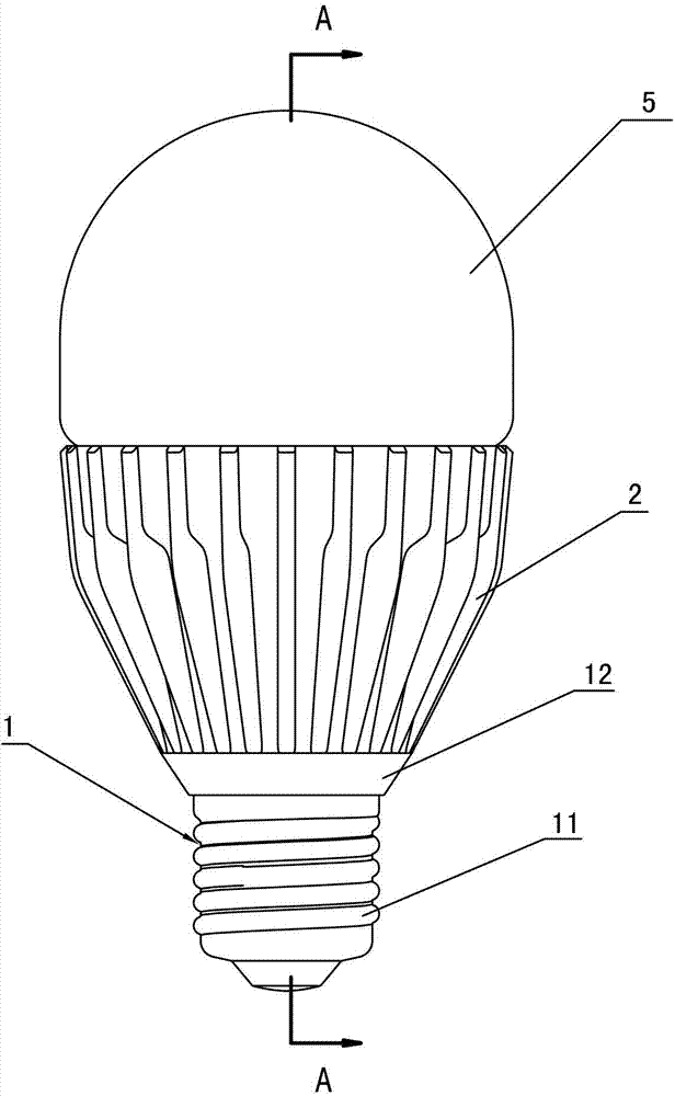
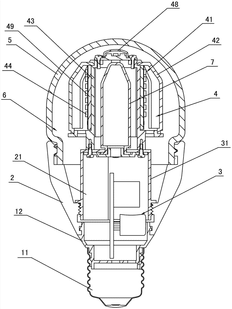
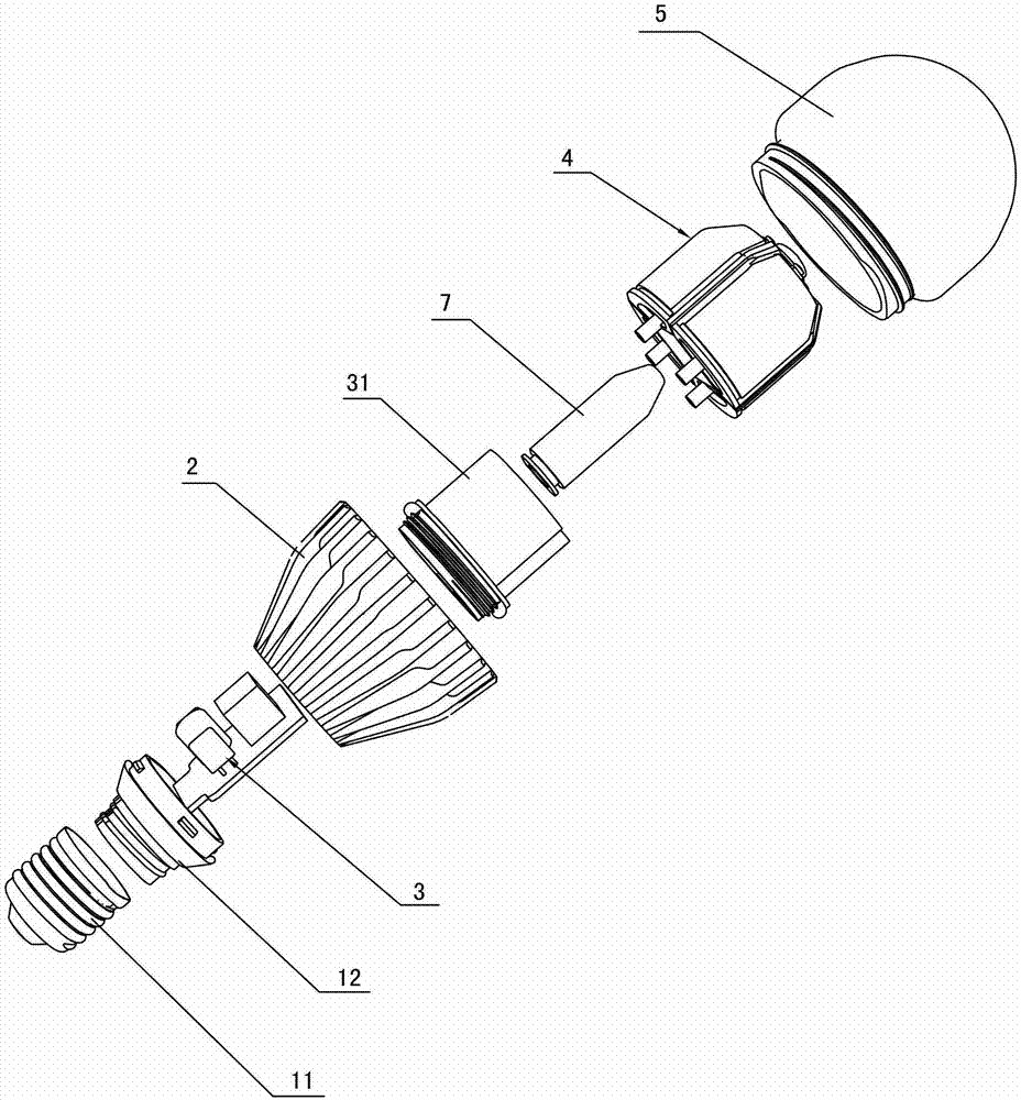
[0027] A liquid heat transfer LED spherical lamp proposed by the present invention, such as figure 1 , figure 2 and image 3 As shown, it includes a lamp cap assembly 1, a hollow radiator 2, a driving power supply 3, a light emitting assembly 4 and a glass cover 5. The lamp cap assembly 1 is mainly composed of a lamp cap 11 and a lamp cap connecting seat 12 connected with the lamp cap 11. The light emitting assembly 4 Located in the glass cover 5, the hollow radiator 2 is provided with a power supply chamber 21, the rear end edge of the hollow radiator 2 is connected to the front edge of the lamp holder 12, the front edge of the hollow radiator 2 is connected to the glass cover 5 The bottom edge of the cover is connected, the driving power 3 is fixed on the lamp cap connecting seat 12 and is electrically connected with the lamp cap 11, the ...


PUM


Abstract

The invention discloses a liquid heat-transfer LED spherical lamp, which comprises a lamp cap assembly composed of a lamp cap and a lamp cap connecting seat, a hollow radiator, a driving power supply, a light-emitting component composed of a light engine module and a high-transparency and temperature-resistant protective cover , Glass cover, the hollow radiator is provided with a power supply chamber, the driving power supply jacket is provided with a sealing cover, the bottom of the sealing cover is sealed and connected with the inner peripheral wall of the hollow radiator, the high light transmission and temperature resistant protective cover and the glass cover The gap between them is connected with the gap between the sealing cover and the hollow heat sink to form a sealed liquid circulation heat dissipation channel. The liquid circulation heat dissipation channel is filled with a high thermal conductivity liquid, so that the LED lamp beads in the light engine module are ignited. The heat heats the high thermal conductivity liquid. After the high thermal conductivity liquid is heated, convection will occur in the liquid circulation cooling channel, and the heat will be dissipated into the air through the glass cover and the hollow radiator. This method has an excellent heat dissipation effect and can effectively reduce the LED The junction temperature of the lamp bead.

Description

technical field [0001] The invention relates to a high-power LED light source, in particular to a liquid heat-transfer LED spherical lamp. Background technique [0002] With the rapid development and maturity of LED (Light Emitting Diode, light-emitting diode) technology, LED light source, as a new type of energy-saving light source, has become more and more More and more occasions use LED light sources instead of traditional light sources for lighting. [0003] As we all know, LED light sources, like traditional light sources, will generate heat during operation. Under the action of external energy, LED light sources will convert 30 to 35% of the energy into light energy through the electrogenic effect of radiation recombination of electrons and holes. The other 65-70% of the energy is converted into heat energy by the lattice vibration that occurs rather than radiative recombination. The LED lamp bead is a light-emitting part that is very sensitive to temperature. Only w...

Claims


Application Information

Patent Timeline
Patent Type & Authority Patents(China)
IPC IPC(8): F21S2/00F21V29/00F21Y101/02F21K9/232F21K9/237F21V29/56F21Y115/10
Inventor 李阳王焕良
Owner 浙江阳光照明灯具有限公司
Why Eureka
Try Eureka