Distributed traffic signal phase difference control structure and adjustment method

A traffic signal and control structure technology, applied in traffic control systems, traffic control systems for road vehicles, instruments, etc., can solve problems such as inability to accurately achieve the target phase, poor adjustment accuracy, and control system scale, so as to strengthen autonomous decision-making at intersections. and the effect of autonomous control

Inactive Publication Date: 2013-02-13
JIANGSU AEROSPACE DAWEI TECH CO LTD
View PDF4 Cites 19 Cited by
  • Summary
  • Abstract
  • Description
  • Claims
  • Application Information

AI Technical Summary

Problems solved by technology

Since the phase difference adjustment and optimization processes are all completed in the central computer, when the number of controlled intersections is large, the central computer has a large overhead, which restricts the further expansion of the system scale
[0009]2) Slow response
Centralized control structures are slow to respond due to the overhead of computing and communication resources
[0010]3) prone to adjustment fluctuations
The fluctuation here refers to the repeated phase difference during the adjustment process, for example, from the phase difference of -10 to 30. The ideal adjustment plan should be that the current phase difference increases monotonously from -10 to 30, but there may be -5, 10, The adjustment process of 0, 10, and 15 has repeated, which slows down the speed of phase difference adjustment
[0011]4) Poor adjustment accuracy
Due to the above fluctuations, sometimes the target phase difference cannot be accurately achieved

Method used


Image

  • Distributed traffic signal phase difference control structure and adjustment method
  • Distributed traffic signal phase difference control structure and adjustment method
  • Distributed traffic signal phase difference control structure and adjustment method

Examples


Embodiment Construction

[0038] The present invention will be further described below in conjunction with drawings and embodiments.
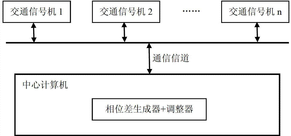
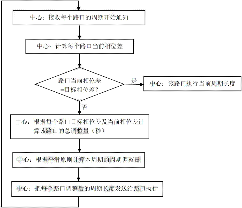
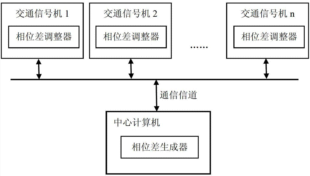
[0039] The core idea of ​​the present invention is to separate the optimal calculation of the phase difference from the adjustment of the phase difference. The optimal calculation of the phase difference is completed by the central computer, and the phase difference adjustment related to the state of each intersection is placed in the local traffic signal at the intersection. It is completed in the control machine, and all traffic signal control machines perform phase difference adjustment calculations in parallel.

[0040] The present invention does not involve target phase difference generation, that is, the optimal calculation of the target phase difference. The distributed phase difference control structure proposed by the present invention and the phase difference adjustment method implemented in the traffic signal control machine will be described in detail below. ...


PUM


Abstract

The invention provides a distributed traffic signal phase difference control structure and a phase difference adjustment method. Two functions of phase difference optimal computation and phase difference adjustment are separated, the phase difference optimal computation is completed by a central computer, the phase difference adjustment relevant to the state of each road junction is completed in a local road junction traffic signal controller, a phase difference adjuster is internally installed in each traffic signal controller, a phase difference generator of the central computer figures out target phase difference of each road junction, then the phase difference generator sends each target phase difference to the traffic signal controller of each road junction, and the traffic signal controllers of road junctions concurrently perform phase difference adjustment computation according to the current phase differences. The distributed traffic signal phase difference control structure and the phase difference adjustment method have the advantages that the central computer can be concentrated on acquisition of optimal phase difference, the phase difference generating algorithm can be carefully selected and optimized, the computing power of numerous road junction controllers can be fully utilized, and simultaneously the autonomous decision-making and autonomous control capabilities of road junctions are enhanced.

Description

technical field [0001] The invention provides a distributed traffic signal phase difference control structure and adjustment method, belonging to the technical field of road traffic signal control. Background technique [0002] Road traffic signal control (traffic light control) is an important technical means to ensure the safety and smoothness of road traffic. Signal cycle (Cycle), green signal ratio (Split) and phase difference (Offset) are the three basic timing parameters for coordinated control of traffic signals . Reasonable signal period length and green-to-signal ratio are the key factors to reduce green light loss time and parking delay at single intersections, while phase difference control is the most important control parameter to realize coordinated control among multiple intersections, reduce parking times and parking delays. [0003] The phase difference is also called the starting time of the green light, which refers to the time difference (unit: second) b...

Claims


Application Information

Patent Timeline
Patent Type & Authority Applications(China)
IPC IPC(8): G08G1/081
Inventor 郑培余李旭东包可为
Owner JIANGSU AEROSPACE DAWEI TECH CO LTD
Why Eureka
Try Eureka