Installation system for proximity switch

An installation system and proximity switch technology, applied in electrical switches, electrical components, circuits, etc., to solve problems such as detection failure, drop in preload, and change in detection distance between proximity switches and the DUT.

Inactive Publication Date: 2013-02-13
ELECTRON CO LTD
View PDF6 Cites 3 Cited by
  • Summary
  • Abstract
  • Description
  • Claims
  • Application Information

AI Technical Summary

Problems solved by technology

[0005] However, when the installation system of the proximity switch is adopted, when the measured piece contacts the proximity piece 003, the fixed bracket 002 that fixes the proximity piece 003 will generate a corresponding vibration, and the installation bracket 001 and the fixed bracket 002 are fixed together, and the vibration transmission to the installation bracket 001, so that the installation bracket 001 also produces corresponding vibrations, and the bolts fixing the proximity switch will loosen due to the vibration, which will lead to a decrease in the pre-tightening force. It will cause the nut to loosen and the threaded connection to fail, resulting in a change in the detection distance between the proximity switch and the DUT, resulting in failure of detection or failure of the proximity switch

Method used


Image

  • Installation system for proximity switch
  • Installation system for proximity switch
  • Installation system for proximity switch

Examples


Embodiment Construction

[0031] In order to make the purpose, technical solutions and advantages of the embodiments of this application clearer, the technical solutions in the embodiments of this application will be described clearly and completely in conjunction with the drawings in the embodiments of this application. Obviously, the described embodiments It is a part of the embodiments of this application, but not all the embodiments. Based on the embodiments in this application, all other embodiments obtained by those of ordinary skill in the art without creative work fall within the protection scope of this application.

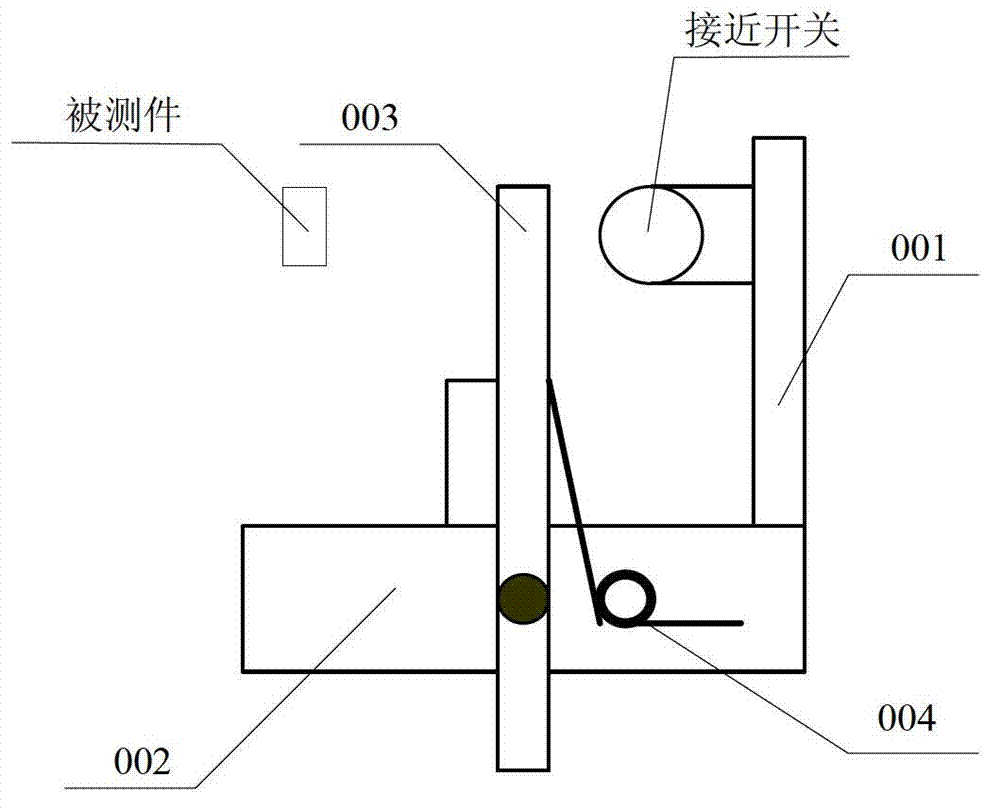
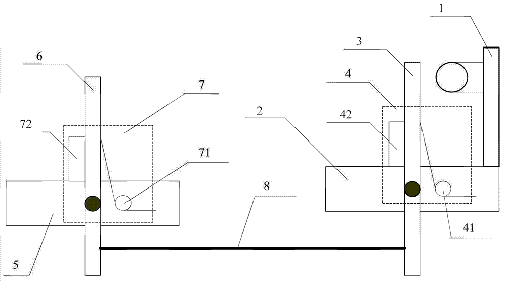
[0032] See figure 2 Shows a schematic structural diagram of an embodiment of a proximity switch installation system provided by the present application, including: a mounting bracket 1, a first fixing bracket 2, a first lever 3, a first reset device 4, a second fixing bracket 5, and a Two levers 6, a second reset device 7 and a flexible connecting piece 8;

[0033] Wherein, the moun...


PUM


Abstract

The invention provides an installation system for a proximity switch. The installation system comprises an installation support 1, a first fixing support 2, a first lever 3, a first reset device 4, a second fixing support 5, a second lever 6, a second reset device 7 and a flexible connection part 8. The first fixing support 2 is vertically and fixedly connected with the installation support 1; the first lever 3 is rotatably connected with the first fixing support 2; the first reset device 4 supports the first lever 3; the second lever 6 is rotatably connected with the second fixing support 5; the second reset device 7 supports the second lever 6; and the second reset device 7 is connected with a first connection end of the first lever 3 and a second connection end of the second lever 6 respectively. The second lever 6 rotates under the thrusting action of a measured part and drives the first lever 3 to rotate through the flexible connection part 8, so that an induction end of the first lever 3 is close to the proximity switch. Due to the flexible action of the flexible connection part 8, shocks transmitted to the proximity switch are small, and the proximity switch cannot be shocked due to the shock. Accordingly, the service life of the proximity switch is increased.

Description

Technical field [0001] This application belongs to the technical field of automatic control, and in particular relates to a proximity switch installation system. Background technique [0002] Proximity switch is a switch that uses the sensitivity of the displacement sensor to approach objects to achieve the purpose of controlling on-off. [0003] At present, the application of proximity switches is very extensive, and they are often used to detect mechanical movement positions. [0004] In the existing technology, such as figure 1 As shown, the installation system of the proximity switch includes: a mounting bracket 001, a fixed bracket 002, a proximity piece 003 and a torsion spring 004. The proximity switch is installed on the mounting bracket 001, the mounting bracket 001 is vertically fixed on the fixed bracket 002, and the proximity piece 003 is also vertically fixed on the fixing bracket 002. The proximity piece 003 is parallel to the mounting bracket 001 and separated by a ce...

Claims


Application Information

Patent Timeline
Patent Type & Authority Applications(China)
IPC IPC(8): H01H9/00H01H3/16
Inventor 谈建功王芳吴召明李振刚王志明王巧鸾许文菊张元华方光深汪春鹏黄鑫刘文奇展杰
Owner ELECTRON CO LTD
Why Eureka
Try Eureka