
Ultrasound diagnostic device

A diagnostic device, ultrasonic technology, applied in the direction of acoustic wave diagnosis, infrasonic wave diagnosis, ultrasonic/sonic wave/infrasonic wave diagnosis, etc. It can solve the problems of hard parts that are difficult to see, surface parts that become hard and invisible, etc.

Inactive Publication Date: 2013-02-13
HITACHI LTD
View PDF8 Cites 5 Cited by
  • Summary
  • Abstract
  • Description
  • Claims
  • Application Information

AI Technical Summary

Problems solved by technology

However, when constructing conventional black-and-white or other shaded three-dimensional tomographic images based on volume rendering, there is a problem that, for example, if there is volume data of other parts in front of the line of sight of the part of interest, it will be invisible or difficult to see. Part of concern
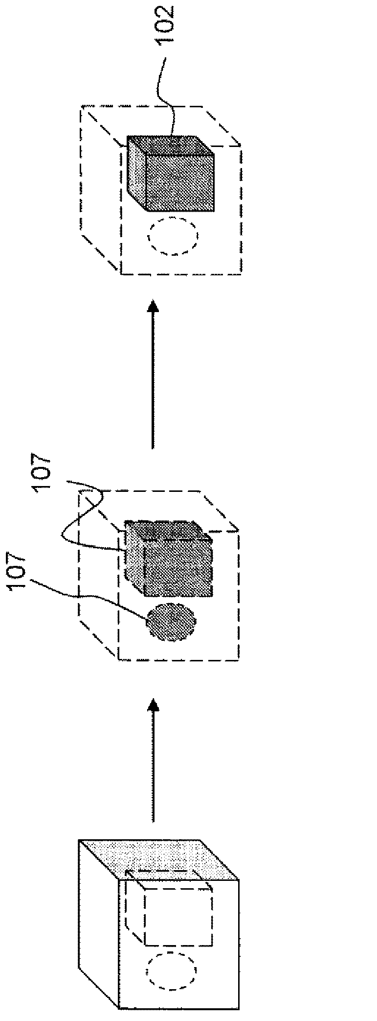
However, tissues such as tumors are generally surrounded by soft tissues and display three-dimensional elastic images, so there is a problem that hard parts are hidden by soft parts and it is difficult to see
In addition, since the surface portion may become hard due to the pressure force that displaces the tissue of the test object, other parts other than the desired part may appear hard, so it is difficult to grasp the part with the desired hardness at a glance.

Method used


Image

  • Ultrasound diagnostic device
  • Ultrasound diagnostic device
  • Ultrasound diagnostic device

Examples


Embodiment 1

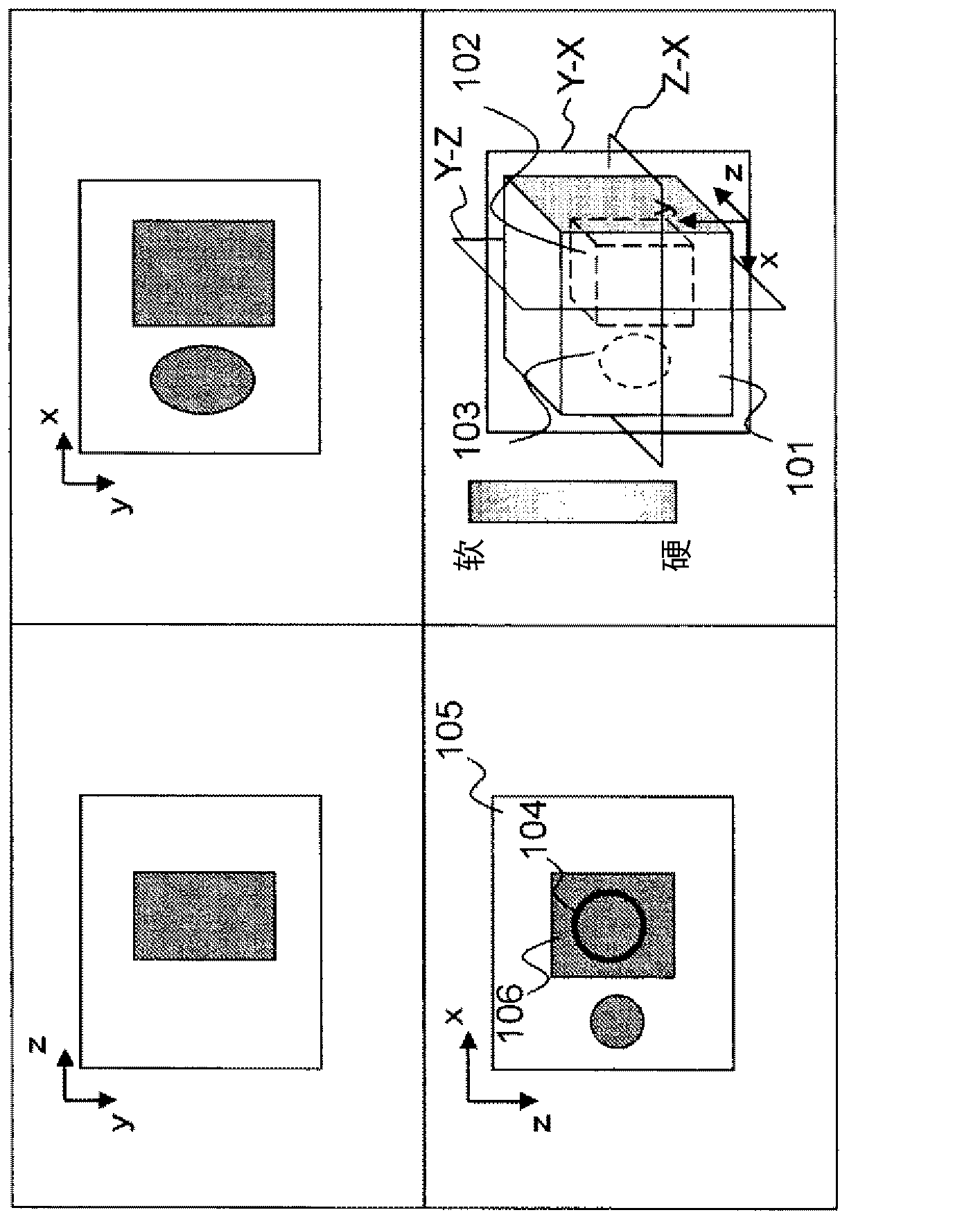
[0068] figure 2 An example of a display image in the first embodiment is shown. As shown in the figure, images on four sides are arranged and displayed. In the figure, the lower right image is a three-dimensional elastic image, and the other images are three-sectional elastic images (elasticity MPR) in three orthogonal three-sections (Y-Z, Z-X, Y-X). In the illustrated example, as shown in a three-dimensional elastic image, it is an example of elastic volume data in which a prismatic hard volume 102 and a spherical hard volume 103 are embedded in a soft volume 101 . Here, a body refers to a tissue mass of a living body. In addition, the prismatic hard body 102 and the spherical hard body 103 are made to have the same hardness. The elastic body data is represented by XYZ coordinates of three orthogonal axes. The operator sets a region of interest 104 on an arbitrary elastic MPR image 106 displayed on the image display 13 via the interface unit 43 . Here, the elastic MPR i...

Embodiment 2

[0083] The second embodiment is a technique in which an input value from the outside is used in the calculation for setting the elastic range in the selected elastic value calculation unit 52 . For example, is it possible to compute only figure 2 The average value of the elastic value of the region of interest 104 and the interface unit 43 is used to input the upper and lower limit values ​​Ls corresponding to "±vs" of the first embodiment by the operator to variably set the elastic range. Thus, the value range of the elasticity value can be freely adjusted by setting the elasticity range of ms±Ls, so that a three-dimensional elasticity image of a site with a specific hardness can be observed.

Embodiment 3

[0085] Figure 4 An example of a display image of the third embodiment is displayed. As shown in the figure, according to the first embodiment, a region of interest 108 is set, and an extracted three-dimensional elastic image 109 is displayed. At this time, the elastic volume data creation unit 40 outputs the extracted volume coordinate information to the elastic multi-frame configuration unit 48 . As a result, the elastic multi-frame configuration unit 48 outputs the extracted volume cross-sectional image as the extracted region 110 in addition to the elastic MPR image of the first embodiment. As a result, the switching combining unit 12 superimposes the extraction region 110 on the elastic MPR image of the first embodiment. In addition, the superimposed display method may be a method of displaying only the outline of the cross-sectional image of the extracted volume, or may be a method of displaying only the extracted volume in a different color.

[0086] In addition, the...


PUM


Abstract

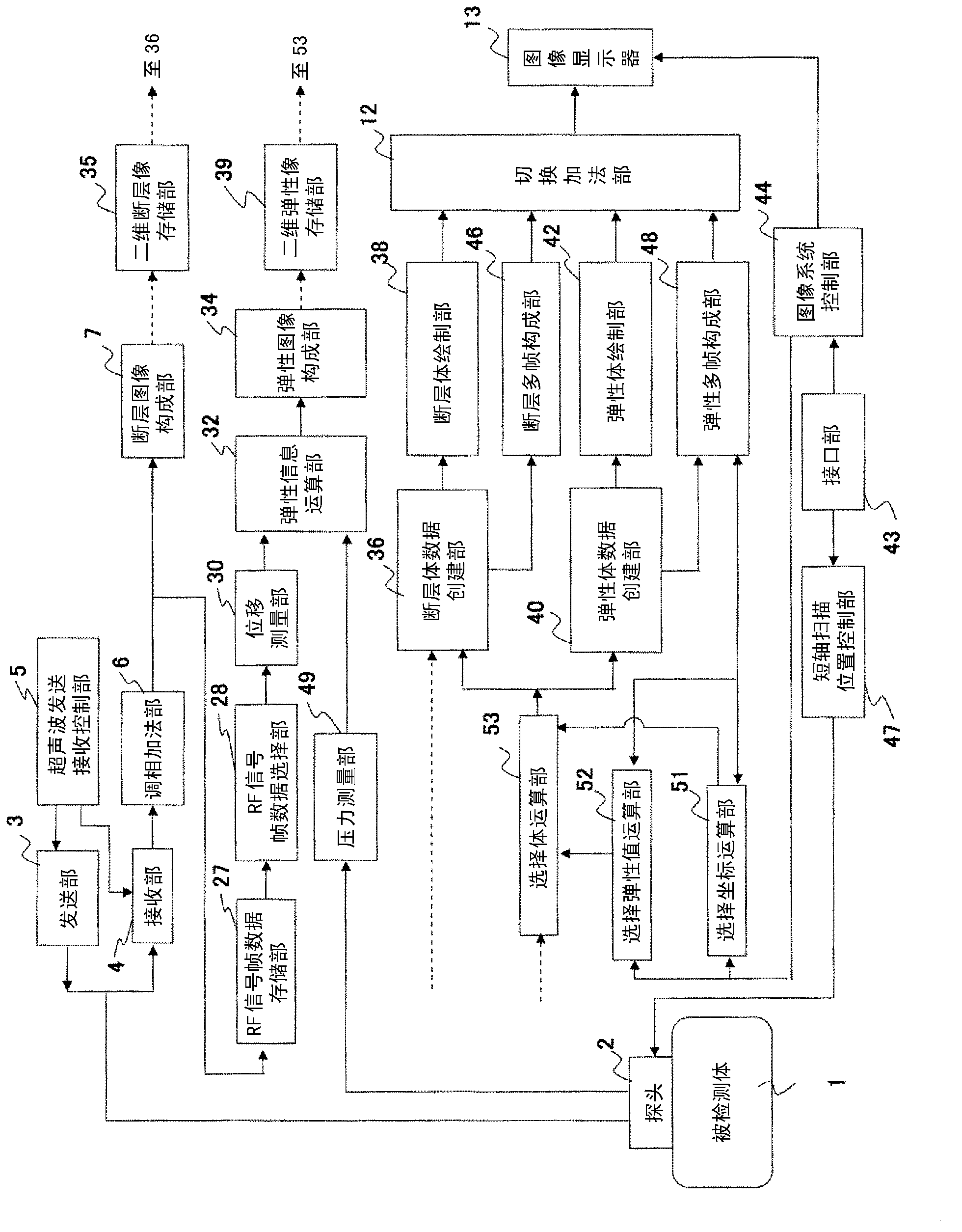
Provided is a configuration including: an elasticity volume data creation unit (40) that creates elasticity volume data on the basis of ultrasound image data that is acquired with ultrasound being transmitted to and received from a specimen; an interface (43) that sets a region of interest in a prescribed space of a space that the elasticity volume data occupies; a selection volume computation unit (53) that extracts a voxel group from elasticity volume data, said voxel group comprising a voxel value within a set elasticity range that is set on the basis of an elasticity value of a voxel of the region of interest; an elasticity volume rendering unit (42) that volume renders either the elasticity volume data of the extracted voxel group or volume data excluding the voxel group and generates a three-dimensional elasticity image; and an image display apparatus (13) that displays the generated three-dimensional elasticity image.

Description

technical field [0001] The present invention relates to an ultrasonic diagnostic apparatus for displaying an ultrasonic image of a diagnostic site in a subject using ultrasonic waves, and more particularly to an ultrasonic diagnostic apparatus for displaying an elastic image such as deformation or elastic modulus as a three-dimensional elastic image. Background technique [0002] A technique has been proposed in which an ultrasonic diagnostic apparatus measures the ultrasonic reflectance of living tissue in a subject using ultrasonic waves, generates and displays a reflectance tomographic image of a diagnostic site in which the ultrasonic reflectance is converted into brightness, In addition, various ultrasonic images are image displayed for diagnosis. For example, it has been proposed to construct tomographic volume data by acquiring a plurality of shaded tomographic images in a subject at intervals, and to construct and display a three-dimensional tomographic image based o...

Claims


Application Information

Patent Timeline
Patent Type & Authority Applications(China)
IPC IPC(8): A61B8/08
CPCA61B8/483A61B8/485A61B8/466A61B8/08
Inventor 猪上慎介林哲矢
Owner HITACHI LTD
Learn More