Device for filtering and separating flow media

A technology of flowing medium and separation unit, applied in the direction of semi-permeable membrane separation, chemical instruments and methods, membranes, etc., can solve the problems of high cost disassembly, cleaning, resealing and reassembly, unreliability, etc., to reduce leakage. Possibility, weight reduction effect

Inactive Publication Date: 2013-02-20
TIG AUTOMATION
View PDF3 Cites 3 Cited by
  • Summary
  • Abstract
  • Description
  • Claims
  • Application Information

AI Technical Summary

Problems solved by technology

If mixing of only 2 parts occurs, the device or a large number of devices connected can no longer be used and must be disassembled, cleaned, resealed and reassembled at high cost
This takes a lot of time, and this is directly reflected in the cost of doing so, not including the unacceptable degree of unreliability of this arrangement of devices

Method used


Image

  • Device for filtering and separating flow media
  • Device for filtering and separating flow media
  • Device for filtering and separating flow media

Examples


Embodiment Construction

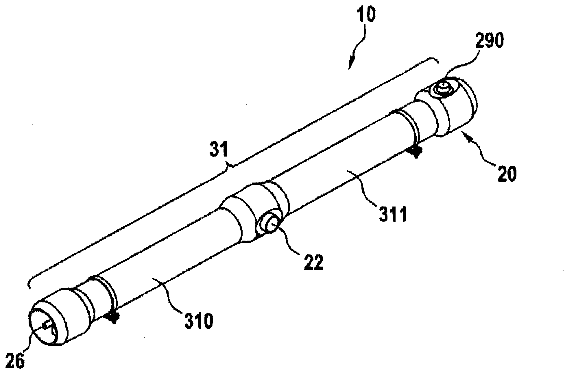
[0031] To illustrate the basic construction of the device 10, first refer to figure 1 and figure 2 .

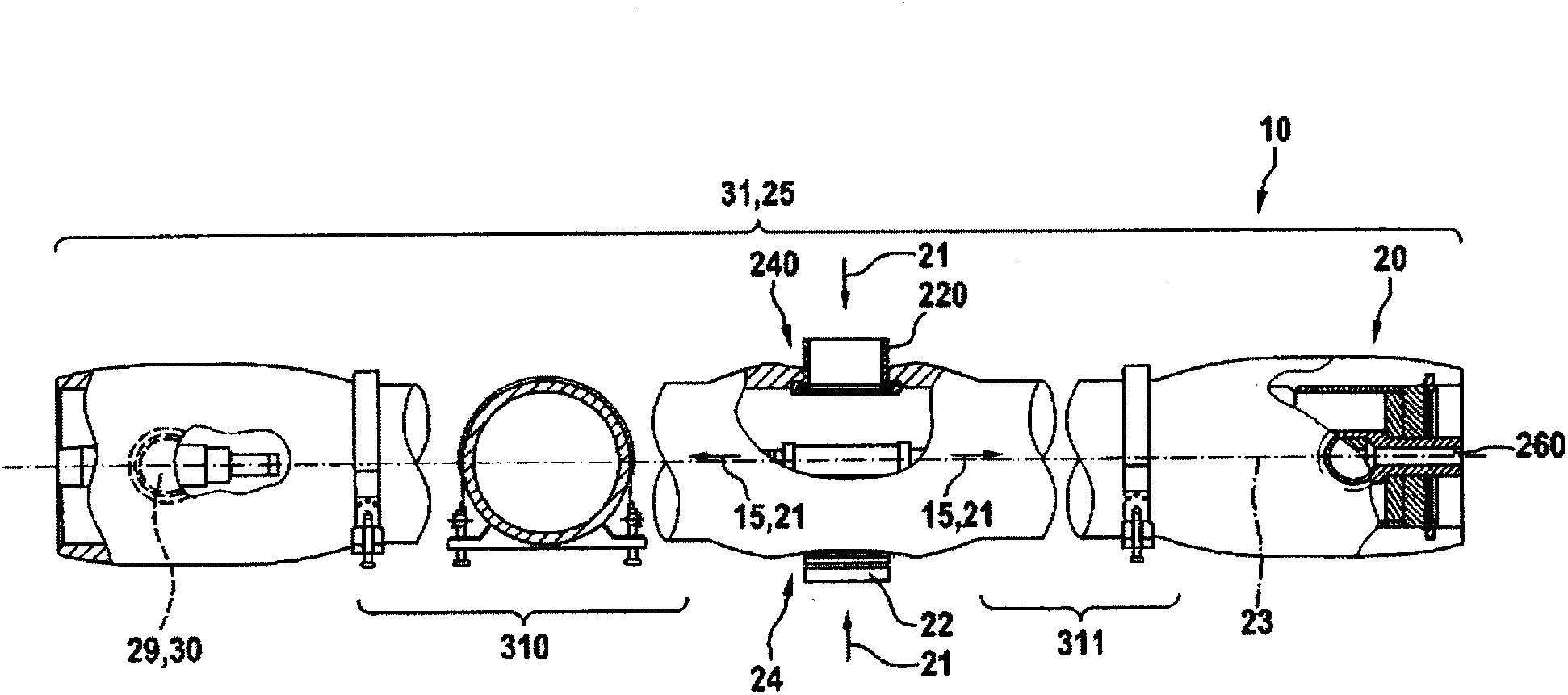
[0032] figure 1 The figure shows a perspective view of the container 20 of the device 10 , wherein the container housing 31 is divided into two container housing elements 310 , 311 . In each of the container housing elements 310, 311 is accommodated a separation unit 11, 110, wherein the separation units 11, 110 generally have the same construction, but the following solution of the device 10 is also possible, that is, the separation unit 11, 110 The separation units 11 , 110 each have different separation specifications for the flow medium 21 , often referred to as fluid or “feed”, which is of different construction and is introduced jointly into the inlet 22 of the two separation units 11 , 110 .

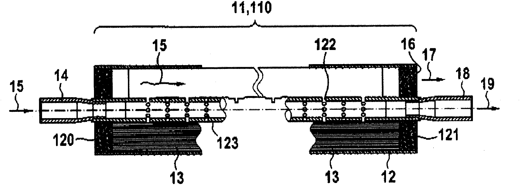
[0033] as in figure 2 The basic construction of the separation unit 11, 110 is known, as exemplified in figure 2 The separation units 11, 110 described in are equipped wi...


PUM


Abstract

A device for filtering and separating flowing media by means of membranes, in particular by the method of ultrafiltration, reverse osmosis and nanofiltration includes a housing in which the membranes are disposed, an inlet for the flowing medium that is carried in the device and is to be separated, and one outlet for carrying out the permeate produced in the device and one outlet for the retentate leaving the device, which substantially forms a separation unit. The device furthermore includes a container in which at least two separation units are received, connected to one another in such a way that for the delivery of the flowing medium to be separated to the at least two separation units, a common inlet is provided.

Description

technical field [0001] The invention relates to a device for filtering and separating flowing media by means of membranes, in particular according to the methods of ultrafiltration, reverse osmosis and nanofiltration, comprising: a housing in which a membrane is arranged; An inlet for the flow medium to be separated and an outlet for the discharge of the permeate produced in the device and an outlet for the retentate in the device; the device essentially consists of a separation unit. Background technique [0002] Devices of this type are known in various embodiments in the prior art and are used in industry, on ships, on offshore exploration platforms, on warships, in automobile construction, in aircraft construction as well In the private sector, it is used for various separation tasks of various fluid mixtures, provided that the fluid mixtures should be able to be separated into their constituent components. For example, devices of the type mentioned at the outset are al...

Claims


Application Information

Patent Timeline
Patent Type & Authority Applications(China)
IPC IPC(8): B01D61/00
CPCB01D63/043B01D2313/20B01D2313/10B01D65/00B01D2319/022B01D61/145B01D61/025B01D61/027B01D61/58B01D63/06B01D2313/2061B01D2313/2062B01D2313/13B01D2313/2011
Inventor 乌多·阿贺拜特
Owner TIG AUTOMATION
Why Eureka
Try Eureka