Real-time thermal printing device

A technology of thermal printing device and thermal printing head, which is applied in printing device, printing, etc., and can solve problems such as not being able to be widely used and limited USB power supply

Inactive Publication Date: 2015-08-19
陆慧玲
View PDF4 Cites 0 Cited by
  • Summary
  • Abstract
  • Description
  • Claims
  • Application Information

AI Technical Summary

Problems solved by technology

However, the power supply of USB is limited after all. This method can only be used for small-sized printers and cannot be widely used.

Method used


Image

  • Real-time thermal printing device

Examples


Embodiment Construction

[0019] The preferred embodiments of the present invention will be described below with reference to the accompanying drawings. It should be understood that the preferred embodiments described herein are only used to illustrate and explain the present invention, but not to limit the present invention.

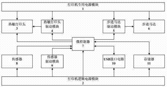
[0020] like figure 1 A real-time thermal printing device shown in the figure includes a printer-specific power module 1, a thermal print head drive module 4, a thermal print head 3, a stepping motor drive module 5, a stepping motor 6, a microcontroller 1, and a sensor drive Module 9, sensor 8, USB interface circuit 10, memory 11 and printer logic power module 2, printer-specific power module 1 provides power for thermal print head drive module 4, thermal print head 3 and stepper motor drive module 5, so The printer logic power module 2 provides power for the microcontroller 7, the sensor drive module 9, the sensor 8, the USB interface circuit 10 and the memory 11, the thermal pr...


PUM


Abstract

The invention discloses a real-time temperature-sensitive printing device. A power supply special for a printer provides power for a temperature-sensitive printing head driving module, a temperature-sensitive printing head and a step motor driving module; a printer logic power supply module provides power for a microcontroller, a sensor driving module, a sensor, a universal serial port (USB) interface circuit and a storage; the temperature-sensitive printing head driving module drives the temperature-sensitive printing head to work, the step motor driving module drives a step motor to run; and the temperature-sensitive printing head driving module, the temperature-sensitive printing head, the step motor driving module, the sensor driving module, the sensor, the USB interface circuit and the storage are all in electric connection with the microcontroller. The power supply special for the printer and the printer logic power supply module respectively provides power for each module in the device, accordingly real-time work of the USB interface circuit is guaranteed, and simultaneously sufficient power is provided for the temperature-sensitive printing head.

Description

technical field [0001] The invention relates to the field of thermal printing, in particular to a real-time thermal printing device. Background technique [0002] The traditional mechanical needle-type printers have large volume, slow printing speed and loud noise, and have gradually withdrawn from the stage of printers. Although the noise of popular inkjet and laser printers is slightly reduced, they are larger in size and do not have the function of real-time printing, which is difficult to meet the needs of some testing instruments such as temperature recorders and medical instruments. [0003] The principle of thermal printers is to coat a light-colored material (usually paper) with a transparent film, and heat the film for a period of time to turn into a dark color (usually black, but also blue). The image is created by heating, which produces a chemical reaction in the film. This chemical reaction is carried out at a certain temperature. High temperatures accelerate...

Claims


Application Information

Patent Timeline
Patent Type & Authority Patents(China)
IPC IPC(8): B41J2/32B41J29/38
Inventor 须小英
Owner 陆慧玲
Why Eureka
Try Eureka