Die change trolley for crawler belt tightening machine
A technology of mold changing trolley and tightening machine, which is applied in the directions of transportation and packaging, manual conveying device, etc., can solve the problems of many people needed, low production efficiency, unsafety, etc., and achieve the effect of fewer people and high production efficiency.
- Summary
- Abstract
- Description
- Claims
- Application Information
AI Technical Summary
Problems solved by technology
Method used
Image

Examples
Embodiment Construction
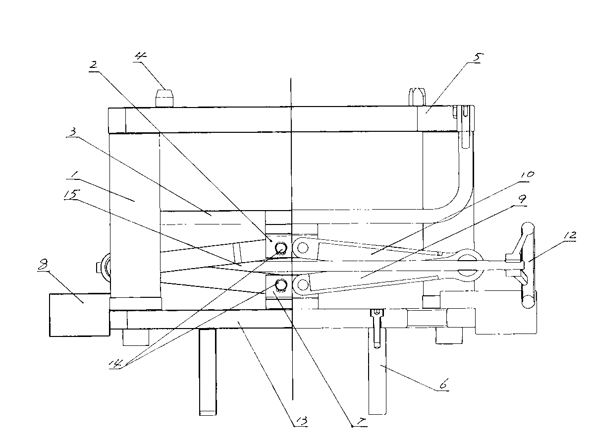
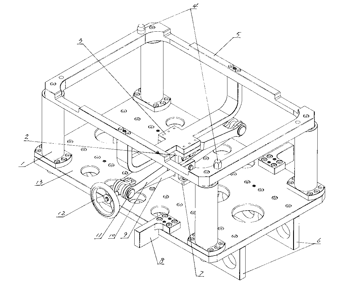
[0013] Such as figure 1 and figure 2 As shown, the mold changing trolley for a crawler tightening machine of the present invention includes a bottom plate 13 and a support frame 5 , and the support frame 5 is located above the bottom plate 13 . Both the bottom plate 13 and the bracket frame 5 are rectangular and equal in length and width. A guide sleeve 1 and a guide rod are arranged between the four corners of the base plate 13 and the support frame 5, the lower ends of the four guide sleeves 1 are respectively fixed on the upper surfaces of the four corners of the base plate 13, and the upper ends of the four guide rods are respectively fixed on the support frame 5. On the lower surfaces of the four corners, the four guide sleeves 1 are respectively corresponding to the four guide rods, and the lower ends of the four guide rods respectively slide into the four guide sleeves 1 .
[0014] The supporting frame 5 contains a rectangular frame, and a U-shaped strut 3 is arrange...
PUM
 Abstract
Description
Claims
Application Information
 - R&D
- Intellectual Property
- Life Sciences
- Materials
- Tech Scout
- Unparalleled Data Quality
- Higher Quality Content
- 60% Fewer Hallucinations
Browse by: Latest US Patents, China's latest patents, Technical Efficacy Thesaurus, Application Domain, Technology Topic, Popular Technical Reports.
© 2025 PatSnap. All rights reserved.Legal|Privacy policy|Modern Slavery Act Transparency Statement|Sitemap|About US| Contact US: help@patsnap.com