Novel carbon tank structure

A carbon canister and support structure technology, applied in the direction of adding non-fuel substances to fuel, engine components, machines/engines, etc., can solve problems such as clogging of carbon canister vents

Inactive Publication Date: 2014-07-30
SAIC-GM-WULING AUTOMOBILE CO LTD
View PDF5 Cites 0 Cited by
  • Summary
  • Abstract
  • Description
  • Claims
  • Application Information

AI Technical Summary

Problems solved by technology

[0005] The present invention is completed in order to solve the deficiencies in the prior art. The purpose of the present invention is to provide a carbon tank structure, which provides a carbon tank with a protective cap, which can prevent dust from entering the carbon tank with the desorption airflow and cause Carbon canister vent clogging problem

Method used


Image

  • Novel carbon tank structure
  • Novel carbon tank structure
  • Novel carbon tank structure

Examples


Embodiment Construction

[0024] The present invention will be described in further detail below in conjunction with the accompanying drawings.

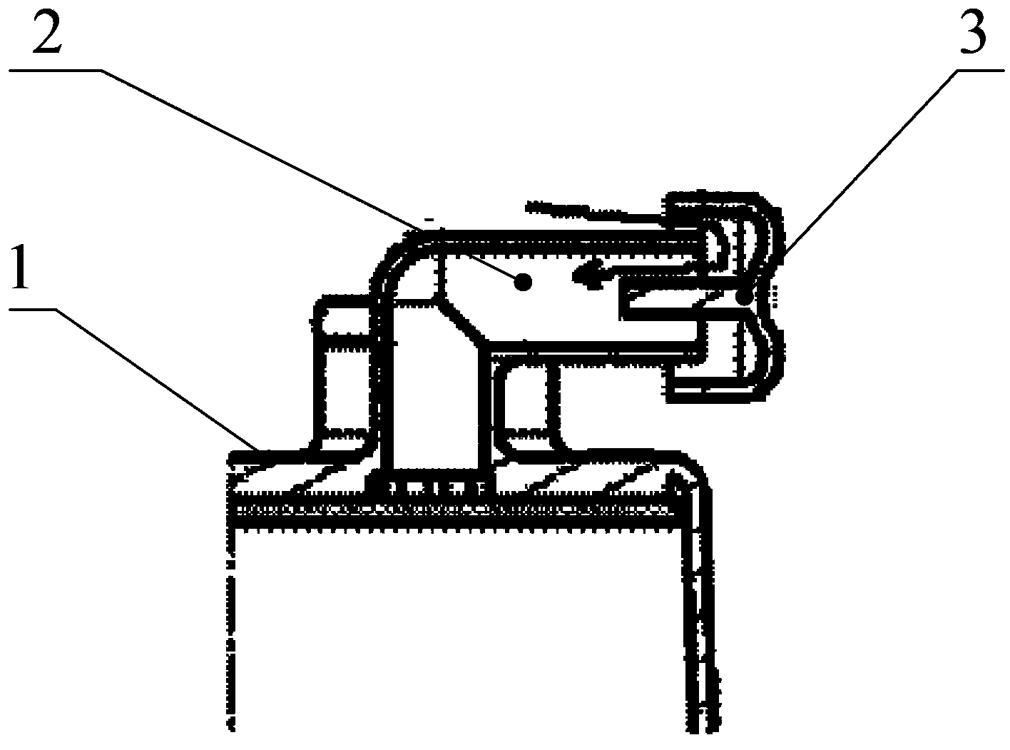
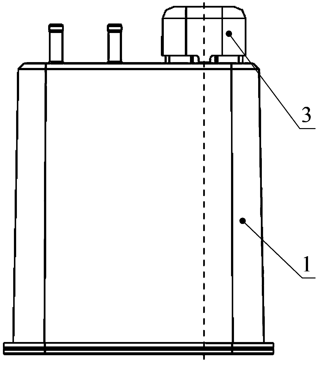
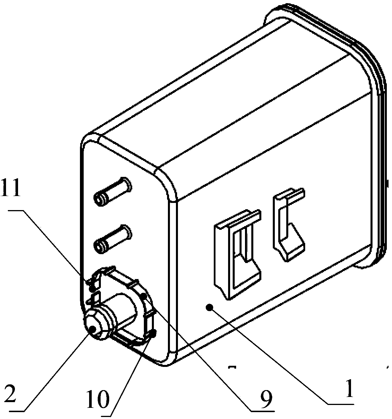
[0025] Such as Figure 2-5 The shown carbon tank structure of the present invention includes a carbon tank main body 1, which is provided with a vent 2 communicating with the outside air, and also includes a protective cap 3, which is covered above the vent; The central part of the protective cap is also protrudingly provided with a buckle 6, the buckle extends into the air vent, and the protective cap is fastened with the air vent through the buckle, ensuring that the protective cap will not fall off when the vehicle is running under various working conditions . A filter element 4 is arranged along its inner wall in the protective cap, and a protruding filter element support structure 5 is also provided at the cover bottom of the protective cap. The filter element support structure clamps the filter element in the space between the protective cap and the fi...


PUM


Abstract

The invention provides a novel carbon tank structure. The novel carbon tank structure comprises a carbon tank main body, wherein the main body is provided with a vent communicated with the outside air. The novel carbon tank structure is characterized by also comprising a protecting cap which covers on the vent; the protecting cap is internally provided with a filtering core along the inner wall; the bottom part of the protecting cap has a convex filtering-core supporting structure; the filtering core is clamped in space between the protecting cap and the filtering-core supporting structure by the filtering-core supporting structure; a fastener which extends into the vent is convexly arranged at the central part of the protecting cap; and the protecting cap is fastened with the vent by the fastener in a clamping manner. The novel carbon tank structure provided by the invention has the advantages that the condition that the protecting cap falls due to vibration in the running process of the whole vehicle can be avoided, the water and sand particles are prevented from directly falling into the carbon tank to block the vent of the carbon tank, and the dust with large particle diameter in the air is prevented from entering the carbon tank along with the air flow to block the vent of the carbon tank.

Description

technical field [0001] The invention relates to the field of automobiles, in particular to a carbon tank structure of an automobile fuel system. Background technique [0002] Gasoline vapor emissions will be produced due to the volatilization of gasoline in the fuel tank where gasoline is stored on the car. Carbon canisters are generally arranged on existing automobiles (gasoline vehicles), such as figure 1 As shown, the canister is filled with granular activated carbon. The carbon tank communicates with the interior of the fuel tank through pipelines, collects and stores the gasoline vapor generated in the fuel tank, and the activated carbon in it absorbs the fuel vapor. When the engine is running, the gasoline vapor stored in the carbon canister will be sucked into the intake system of the engine along with the high-speed airflow of the canister vent and participate in combustion to reactivate the carbon canister [0003] (desorption process). [0004] There are air ve...

Claims


Application Information

Patent Timeline
Patent Type & Authority Patents(China)
IPC IPC(8): F02M25/08
Inventor 唐基荣吕兆平赵艳芳
Owner SAIC-GM-WULING AUTOMOBILE CO LTD
Why Eureka
Try Eureka