Automatic falling device of wine bottle bracket

A rack device and bracket technology, which is applied in the field of automatic cutting, can solve the problems of time-consuming, labor-intensive and low-efficiency, and achieve the effects of noise reduction, high efficiency and strong practicability.

Inactive Publication Date: 2019-06-25
JIANGSU ZUIKAIXIN LIQUOR CO LTD
View PDF0 Cites 0 Cited by
  • Summary
  • Abstract
  • Description
  • Claims
  • Application Information

AI Technical Summary

Problems solved by technology

[0003] The technical problem to be solved by the present invention is that the wine bottle brackets in the prior art can only be sorted and collected manually after production, which is time-consuming, laborious and inefficient.

Method used


Image

  • Automatic falling device of wine bottle bracket
  • Automatic falling device of wine bottle bracket
  • Automatic falling device of wine bottle bracket

Examples


Embodiment 1

[0025] After the produced wine bottle brackets are transported out, the wine bottle brackets need to be manually rearranged before returning to the spraying room for the next batch of spraying, which is time-consuming and laborious, and the efficiency is low. Therefore, it is necessary to provide a device capable of automatically sorting and collecting wine bottle brackets to improve production efficiency.

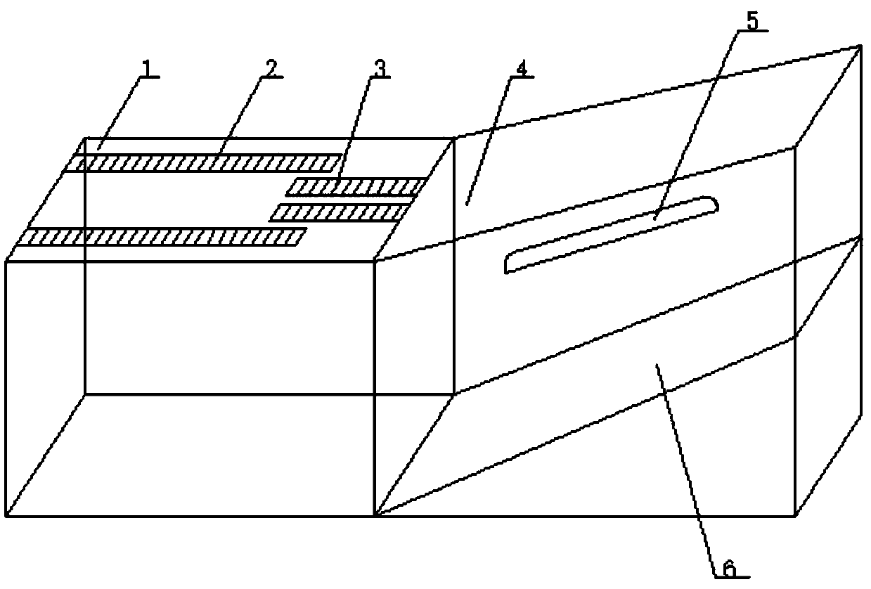
[0026] In order to solve the above technical problems, the present invention provides an automatic unloading device for wine bottle brackets. refer to figure 2 As shown, the automatic unloading device of the wine bottle bracket includes a transfer box 1 and a pick-up box 4, the pick-up box 4 is connected to the transfer box 1 at an angle, and the connecting end of the pick-up box 4 Lower than the non-connecting end; the transmission box 1 is provided with a first transmission assembly and a second transmission assembly that move in the same direction and can be adjusted ...

Embodiment 2

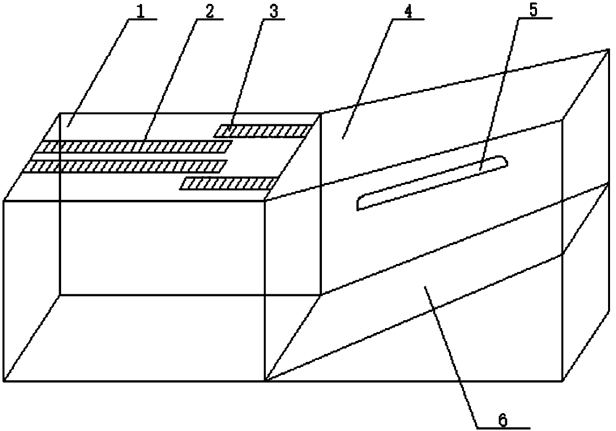
[0035] refer to image 3 As shown, different from Embodiment 1, this embodiment provides an installation diagram of another mutual positional relationship between the first transmission assembly and the second transmission assembly, and the second transmission chain 3 is arranged on the first The outside of the transmission chain 2.

Embodiment 3

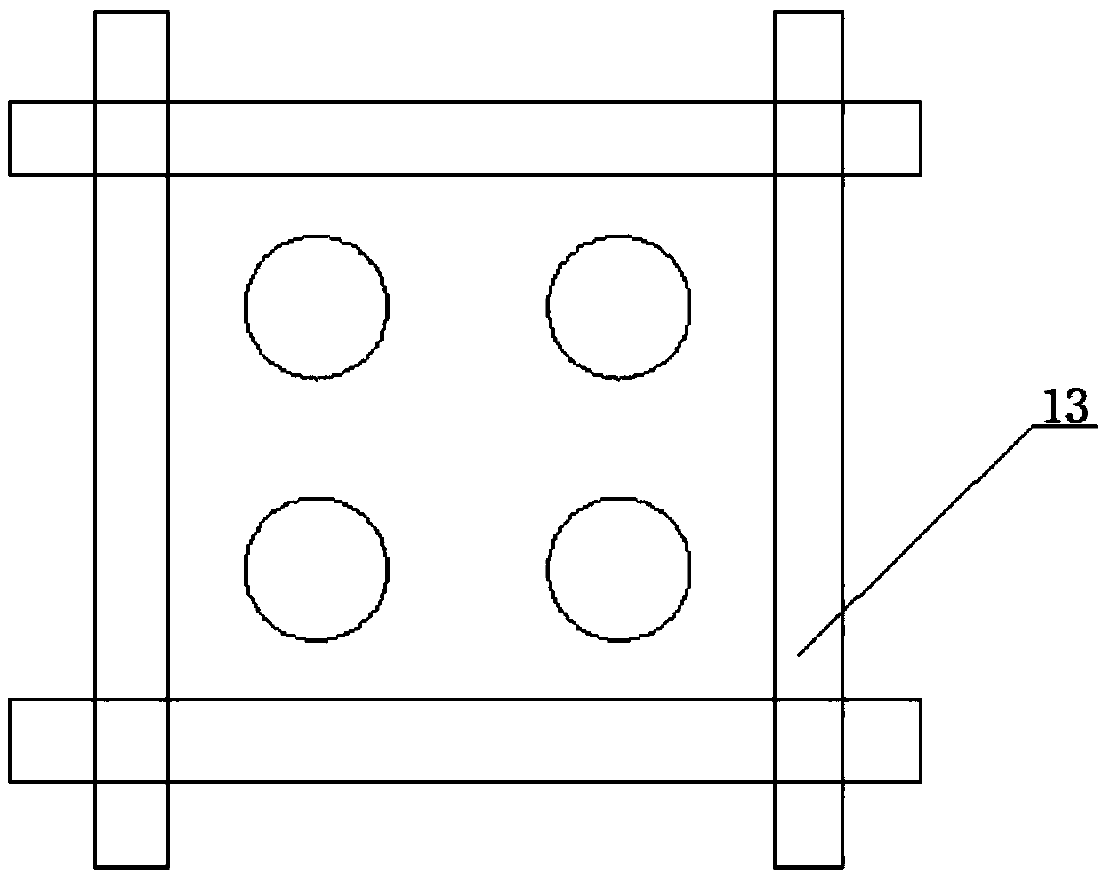
[0037] The difference between this embodiment and Embodiment 1 is that this embodiment provides another connection method between the receiving guide rail 5 and the receiving box 4, refer to Figure 5 As shown, the receiving guide rail 5 includes a connection side wing and a support frame 9, the support frame 9 is welded on the connection side wing, and the connection side wing includes a first side wing 7 and a second side wing that are symmetrically arranged relative to the support frame 9. Two side wings 10, the first side wing 7 and the second side wing 10 respectively have through holes 8. The same through hole is also arranged on the said receiving box 4, and the through hole 8 on the said first side wing 7 and the second side wing 10 is passed through the screw to cooperate with the through hole on the said receiving box 4, and the said receiving box 4 The receiving guide rail 5 is fixed on the receiving box 4 . The receiving guide rail 5 can slide on the through hole ...


PUM


Abstract

The invention relates to the technical field of automatic falling, and discloses an automatic falling device of a wine bottle bracket. The automatic falling device comprises a conveying box and a material receiving box, wherein the material receiving box is in angle connection with the conveying box, and the connecting end of the material receiving box is lower than the non-connecting end of the material receiving box; a first conveying assembly and a second conveying assembly which move in the same direction are arranged on the conveying box, the speed of the second conveying assembly is adjustable, bearing guide rails and a conveying belt are arranged in the material receiving box, the bearing guide rails are symmetrically arranged on side plates of the material receiving box, and the conveying belt is arranged below the bearing guide rails. According to the automatic falling device, the problems that in the prior art, the wine bottle bracket for spraying is manually collected, timeand labor are wasted, and the efficiency is low are solved, the device for automatically collecting the wine bottle bracket is provided, manual sorting and collecting of the wine bottle bracket are omitted, time and labor are saved, the efficiency is high, and the practicability is high.

Description

technical field [0001] The invention relates to the technical field of automatic unloading, and discloses an automatic unloading device for wine bottle brackets. Background technique [0002] Wine bottles are usually packaged by shipping brackets and then transferred. The packaging method of wine bottles directly affects the transportation safety and cost of wine bottles. Currently, commonly used wine bottle brackets are generally figure 1 The above-mentioned bracket in the form of a cross with a bottom sealing plate is packaged and consigned. This structure is convenient for placing wine bottles, has high stability, and at the same time has a simple structure, is easy to operate, and saves manpower and material resources. Therefore, the demand for this kind of bracket is relatively large, and mass production is required. At present, in the process of producing brackets, it is necessary to manually arrange the produced brackets, which is time-consuming and laborious, and the...

Claims


Application Information

Patent Timeline
IPC IPC(8): B65G57/112
Inventor 张金龙
Owner JIANGSU ZUIKAIXIN LIQUOR CO LTD
Why Eureka
Try Eureka