Bladeless fan

A bladeless fan, impeller cover technology, applied in liquid fuel engines, non-displacement pumps, mechanical equipment, etc., can solve problems such as large airflow transmission loss

Inactive Publication Date: 2013-02-20
任文华
View PDF1 Cites 4 Cited by
  • Summary
  • Abstract
  • Description
  • Claims
  • Application Information

AI Technical Summary

Problems solved by technology

However, the airflow transmission loss of this kind of f...

Method used


Image

  • Bladeless fan
  • Bladeless fan
  • Bladeless fan

Examples


Embodiment Construction

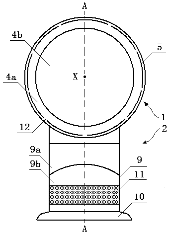
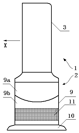
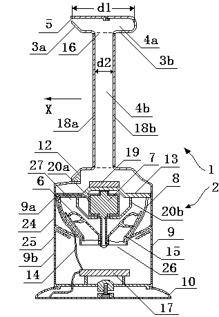
[0025] Figure 1 is a schematic view of the fan of the present invention viewed from the front of the device, figure 2 yes figure 1 Side view of the fan shown, image 3 shown figure 1 The internal structure of the fan shown. from Figure 1 to Figure 3 As can be seen in the figure, this fan includes a base 2 and a nozzle 1 arranged on the base 2; the base 2 includes a base body 9 and a base 10 located below the base body, and the base body 9 has a housing 24, 25 , the housing 25 is provided with an air inlet 11, the air inlet 11 is in the form of a grid hole; the base body 9 includes the impeller cover 8 located in the housing 24, 25, the impeller 6 located in the impeller cover, and the driving impeller 6 to rotate The motor 7, the fixing device 13 and the cable 14; the impeller cover 8 has an air inlet 26 and an air outlet 27; the impeller 6 includes a substantially conical hub, a plurality of blades connected to the hub, and an outer side connected to the plurality of b...


PUM


Abstract

A bladeless fan comprises a spray nozzle and a generation device for generating air flow passing through the spray nozzle. The spray nozzle comprises a cavity and a venting hole, the generation device comprises an impeller cover, impellers arranged in the impeller cover, a motor for driving the impellers to work, a fixing device for fixing the motor, and a cable connected with the motor, wherein the fixing device comprises a first fixing piece connected with the motor and a plurality of connecting rods, one end of each connecting rod is connected with the first fixing piece, and the other end of each connecting rod is connected with the impeller cover. The bladeless fan has the advantages of being low in air flow transmission loss, simple in structure and the like.

Description

technical field [0001] The invention relates to a fan. In particular, but not exclusively, the present invention relates to a domestic fan, such as a domestic desk fan, for increasing air circulation and air flow in homes, offices and other environments. Background technique [0002] A traditional household fan typically consists of a motor and a set of blades or impellers that are driven in rotational motion by the motor. The set of blades is typically located within a cage that allows airflow to pass through, yet prevents human access to the rotating blades. But in some cases, this kind of fan also has the danger that the human body touches the group of rotating blades. [0003] The Chinese patent application with publication number CN 101825105A published on September 8, 2010 (application number: 201010130001.X) discloses a fan without exposed blades, which includes a base and a nozzle installed on the base. The base includes an outer shell and a generating device for ...

Claims


Application Information

Patent Timeline
IPC IPC(8): F04B41/06F04D25/08F04D29/66F04D29/00F04F5/46
Inventor 任文华
Owner 任文华
Why Eureka
Try Eureka