Bladeless fan

A technology of bladeless fan and housing, which is applied in the directions of liquid variable capacity machines, non-variable capacity pumps, variable capacity pump components, etc., and can solve the problems of large airflow transmission loss and large base in the nozzle

Inactive Publication Date: 2014-05-21
任文华
View PDF5 Cites 21 Cited by
  • Summary
  • Abstract
  • Description
  • Claims
  • Application Information

AI Technical Summary

Problems solved by technology

However, the base of this type of fan is relatively large, and the

Method used


Image

  • Bladeless fan
  • Bladeless fan
  • Bladeless fan

Examples


Embodiment Construction

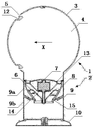
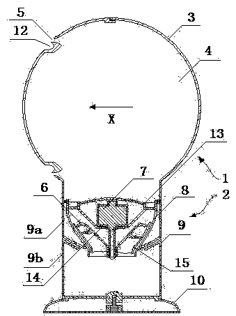
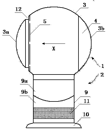
[0036] Figure 1 is a schematic view of the fan of the present invention viewed from the front of the device, figure 2 yes figure 1 Side view of the fan shown, image 3 shown figure 1 The internal structure of the fan shown. From Figure 1 to Figure 3 It can be seen that the fan includes a base 2 and a nozzle 1 arranged on the base 2; the base 2 includes a base body 9 and a base 10 located below the base body, the base body 9 has a side wall, and the side wall The wall includes an air inlet 11 in the form of a grid hole; the base body 9 includes an impeller housing 8, an impeller 6 located inside the impeller housing and a motor 7 for driving the impeller in rotation, the impeller 6 comprising a substantially conical hub, Connected to a plurality of blades on the hub and a shroud 15 connected to the outer edges of the plurality of blades, the motor 7 is fixed on a fixing 14 connected to a diffuser 13 located downstream of the impeller 6, the diffuser 13 is fixed on the i...


PUM

PropertyMeasurementUnit
Depthaaaaaaaaaa

Abstract

A bladeless fan comprises a spraying nozzle (1) and a device for generating airflow passing through the spraying nozzle, the spraying nozzle comprises a shell (3) roughly in the shape of a sphere, a cavity (4) located in the shell, and an exhaust port (5) formed in the shell, wherein the shell is provided with a pit (12) located on the downstream portion of the exhaust port. Transmission loss of airflow of the fan is low, and the fan is beautiful in shape.

Description

technical field [0001] The invention relates to a fan. In particular, but not exclusively, the present invention relates to a domestic fan, such as a domestic desk fan, for increasing air circulation and air flow in homes, offices and other environments. Background technique [0002] A traditional household fan typically consists of a motor and a set of blades or impellers that are driven in rotational motion by the motor. The set of blades is typically located within a cage that allows airflow to pass through, yet prevents human access to the rotating blades. But in some cases, this kind of fan also has the danger that the human body touches the group of rotating blades. [0003] On November 15, 1949, U.S. Patent US2488467 disclosed a fan without exposed blades. This fan includes a base and an annular nozzle arranged on the base. The base includes a motor and fan blades driven by the motor. The fan blades provide airflow to the annular nozzle, which includes an annular c...

Claims


Application Information

Patent Timeline
IPC IPC(8): F04B41/06F04B39/12
CPCF04D25/08F04F5/16
Inventor 任文华
Owner 任文华
Why Eureka
Try Eureka