Resource allocation method and device of control channel information

A technology for controlling channels and controlling information, applied in wireless communication, electrical components, etc., to achieve the effects of increasing blind detection space, enhancing scheduling flexibility, and realizing dynamic changes

Active Publication Date: 2013-02-20
江苏慧煦电子科技有限公司
View PDF3 Cites 19 Cited by
  • Summary
  • Abstract
  • Description
  • Claims
  • Application Information

AI Technical Summary

Problems solved by technology

[0011] In view of this, the main purpose of the present invention is to provide a resource configuration method and device for a control channel, which is used to solve the problem of configuration and transmission of the enhanced physical downlink control channel ePDCCH

Method used


Image

  • Resource allocation method and device of control channel information
  • Resource allocation method and device of control channel information
  • Resource allocation method and device of control channel information

Examples


Embodiment 1

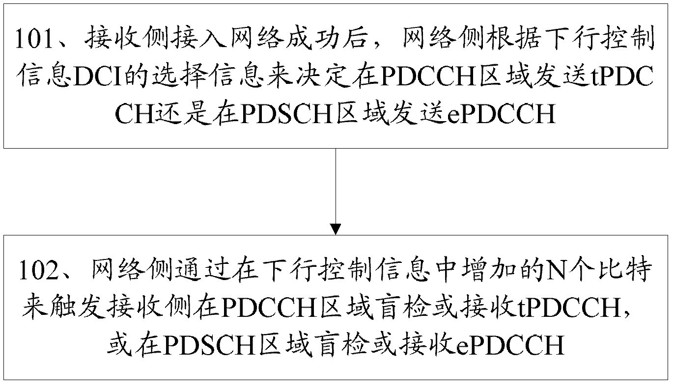
[0045] The network side adds N bits to the downlink control information DCI to trigger whether the receiving side needs to blindly detect tPDCCH in the PDCCH region or blindly detect ePDCCH in the PDSCH region in the next subframe. Specific methods such as figure 1 Shown:

[0046] Step 101: After the receiving side successfully accesses the network, the network side decides whether to send tPDCCH in the PDCCH region or send ePDCCH in the PDSCH region according to the selection information of the downlink control information DCI;

[0047] When the receiving side accesses the network, it obtains system broadcast scheduling information and the like in the PDCCH area. After the receiving side successfully accesses the network, the network side can decide to send DCI (tPDCCH) in the PDCCH area or send DCI in the PDSCH region according to the DCI selection information such as the environment of the receiving side, the channel condition of the receiving side, and the load of the sys...

Embodiment 2

[0051] The network side adds 1 bit to the downlink control information DCI to indicate whether the receiving side needs to blindly detect DCI in the PDCCH region or in the PDSCH region in the next subframe. When the receiving side accesses the network, consider obtaining system broadcast scheduling information in the PDCCH area. After the receiving side successfully accesses the network, the network side can decide to send DCI (tPDCCH) in the PDCCH area or send DCI in the PDSCH region according to the DCI selection information such as the environment of the receiving side, the channel condition of the receiving side, and the load of the system's downlink control channel. Regional transmission DCI (ePDCCH).

[0052] The network side may trigger ePDCCH transmission in subframes after the nth subframe in the nth subframe according to the DCI selection information. The receiving side performs blind detection in the nth subframe or receives the trigger information sent by the netw...

Embodiment 3

[0054] The network side triggers the receiving side to adopt ePDCCH blind detection or receive downlink control information by reusing the downlink control information DCI, such as DCI Format 1C.

[0055] When the receiving side accesses the network, consider obtaining system broadcast scheduling information in the PDCCH area. After the receiving side successfully accesses the network, the network side can decide to send DCI (tPDCCH) in the PDCCH area or send DCI in the PDSCH region according to the DCI selection information such as the environment of the receiving side, the channel condition of the receiving side, and the load of the system's downlink control channel. Regional transmission DCI (ePDCCH).

[0056] The network side may trigger ePDCCH transmission in subframes after the nth subframe in the nth subframe according to the DCI selection information. The receiving side performs blind detection in the nth subframe or receives the trigger information sent by the networ...


PUM


Abstract

The invention discloses a resource allocation method and device of control channel information and aims at solving the allocation and sending problems of an enhanced downlink control channel enhanced physical downlink control channel (e PDCCH). A network side triggers a receiving side to blindly test in a PDCCH area or receive a traditional (t) PDCCH, or blindly test in a physical downlink shared channel (PDSCH) area or receive the e PDCCH through N bits increased in downlink control information in aperiodic trigger mode; and/or the network side instructs the receiving side the time domain of the e PDCCH in the PDSCH area needing blind test and/or the frequency domain position range in aperiodic trigger mode. The resource allocation method and device enable the e PDCCH to obtain sufficient frequency diversity gain and scheduling gain, enlarge the blind test space of the e PDCCH without obviously increasing blind test complexity, and increase scheduling flexibility due to the fact that the blind test space of the e PDCCH can be dynamically changed.

Description

technical field [0001] The present invention relates to a long term evolution advanced system (Long Term Evolution Advanced system, LTE-Advanced), in particular to a resource allocation method and device for control channel information in LTE-Advanced. Background technique [0002] In LTE Release8 / 9, in order to measure the quality of the channel and demodulate the blind detection or received data symbols, CRS (Common Reference Signal, common reference signal) is designed, and UE (User Equipment, user equipment) can perform CRS through CRS Channel measurement, so as to determine the UE to perform cell reselection and handover to the target cell, and measure the channel quality in the UE connection state. When the interference level is high, the physical layer can be disconnected through high-level related wireless link connection failure signaling Open the connection. In LTE10, in order to further improve the average spectrum utilization rate of the cell, the spectrum utili...

Claims


Application Information

Patent Timeline
Patent Type & Authority Applications(China)
IPC IPC(8): H04W72/04
Inventor 郭森宝孙云锋张峻峰
Owner 江苏慧煦电子科技有限公司
Why Eureka
Try Eureka