Systems and methods for communications through materials

a communication system and material technology, applied in the field of systems and methods for communication through materials, can solve the problems that the antenna system, if possible, cannot be practical, and the technique cannot effectively achieve the effect of appreciable distance without impractically very large antennas, so as to reduce the physical size of the electrical conductor of the antenna, reduce the physical size of the electrical conductor, and reduce the effect of radiated efficiency

Inactive Publication Date: 2009-01-29
MENNER JOHN
View PDF1 Cites 6 Cited by
  • Summary
  • Abstract
  • Description
  • Claims
  • Application Information

AI Technical Summary

Benefits of technology

[0005]An advantage of the embodiments described herein is that they overcome the disadvantages and meet the needs described above. These advantages and others are provided by an antenna system for communicating through materials. The antenna system includes an antenna conductor that transmits an electromagnetic field bi-directionally, a lens layer that compresses the wavelength of the electromagnetic field and a backing material that re-directs the electromagnetic field in a chosen direction. The re-directed, compressed electromagnetic field has a sufficient frequency and power for the antenna system to effectively sense or transmit through a chosen material.

Problems solved by technology

Currently available techniques cannot effectively accomplish this for any appreciable distance without impractically very large antennas if even then.
Such antenna systems, if possible, would not be practical due to size and cost for most situations, prohibitively expensive, massive, non-transportable, etc.

Method used


Image

  • Systems and methods for communications through materials
  • Systems and methods for communications through materials
  • Systems and methods for communications through materials

Examples


Embodiment Construction

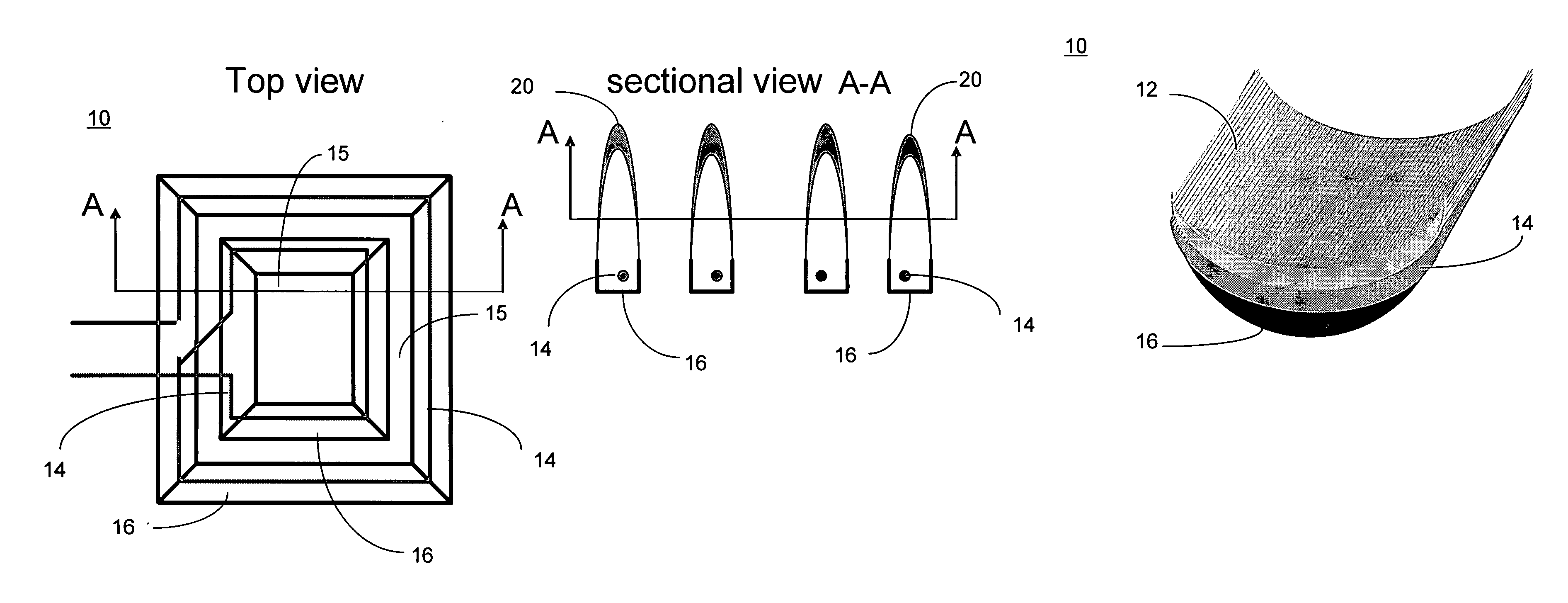
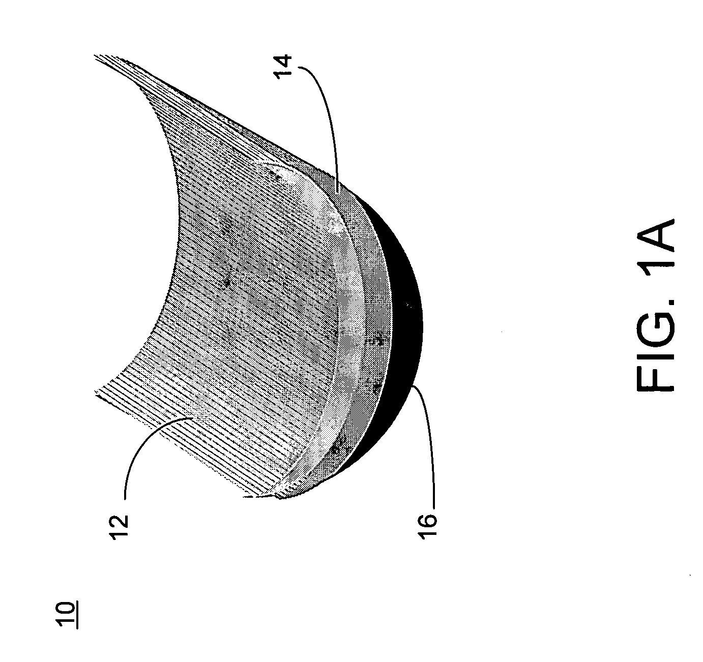
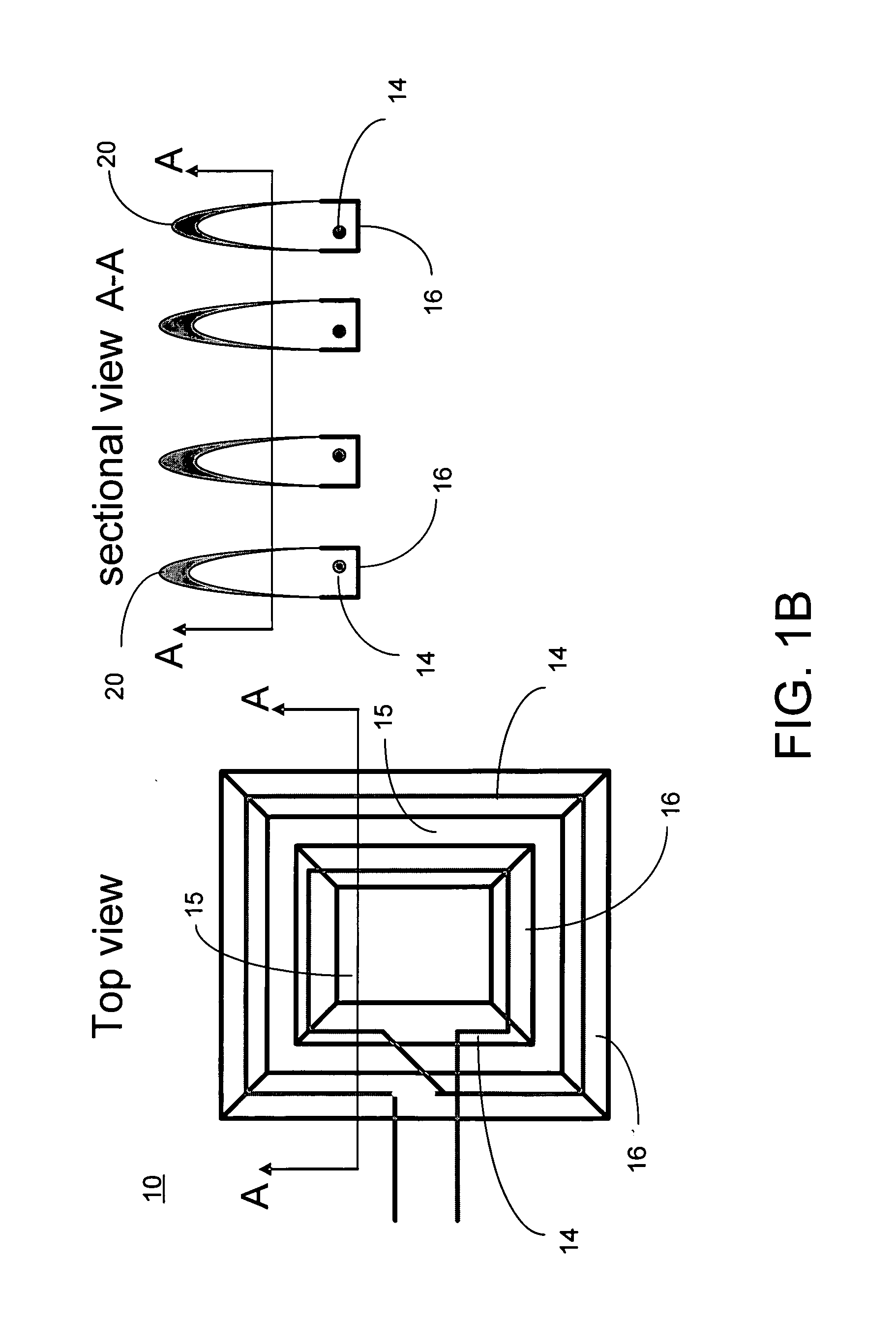
[0015]Described herein are systems and methods for communicating through materials. Embodiments provide an antenna that enables such communications. In order to enable such communications, one goal of the embodiments described herein is to reduce the physical size of the electrical conductor needed to match to the radiated wavelength. This can be accomplished by reducing the size of the electromagnetic wavelength through wave compression in the antenna structure itself.

[0016]Another goal achieved by the embodiments described herein is to further reduce the physical size of the antenna conductor by creating non-mutually inductive antenna conductor segments; this increases the effective length of the antenna. If segments of the antenna conductor are mutually inductive, they shorten the effective conductor length because of the field influence each mutually inductive segment has on each other. Embodiments described herein accomplish this (the non-mutually inductive antenna conductor se...


PUM


Abstract

A system and a method for communicating through materials are provided. One exemplary system is an antenna system for communicating through materials. The antenna system includes an antenna conductor that transmits an electromagnetic field bi-directionally, a lens layer that compresses the wavelength of the electromagnetic field and a backing material that re-directs the electromagnetic field in a chosen direction. The re-directed, compressed electromagnetic field has a sufficient frequency and power for the antenna system to effectively sense or transmit through a chosen material.

Description

CROSS REFERENCE TO RELATED APPLICATION(S)[0001]This application claims priority from U.S. Provisional Application 60 / 961,814 filed Jul. 24, 2007 entitled “COMMUNICATIONS THROUGH MATERIALS” the content of which is incorporated herein in its entirety to the extent that it is consistent with this invention and application.BACKGROUND[0002]In many real life emergency cases for example in mine explosions, it is necessary to communicate through some electrically lossy or conductive material such as clay or wet earth directly to the surface for rescue or directly from the surface into a mine, deep underground. In other cases, it may be important to have sensors from deep wells communicate information directly to the ground or sea surface. When underground in mines, caves, or inside buildings and cities, it is desired to communicate with first responders. Currently available techniques cannot effectively accomplish this for any appreciable distance without impractically very large antennas i...

Claims


Application Information

Patent Timeline
Patent Type & Authority Applications(United States)
IPC IPC(8): H01Q19/06
CPCH01Q1/04H01Q7/00H04B13/00H01Q19/10H01Q19/06
Inventor MENNER, JOHN
Owner MENNER JOHN
Why Eureka
Try Eureka