Method and device for monitoring the function of an exhaust-gas sensor

US20130269316A1Active Publication Date: 2013-10-17ROBERT BOSCH GMBH

Image

  • Method and device for monitoring the function of an exhaust-gas sensor
  • Method and device for monitoring the function of an exhaust-gas sensor
  • Method and device for monitoring the function of an exhaust-gas sensor

Examples


Embodiment Construction

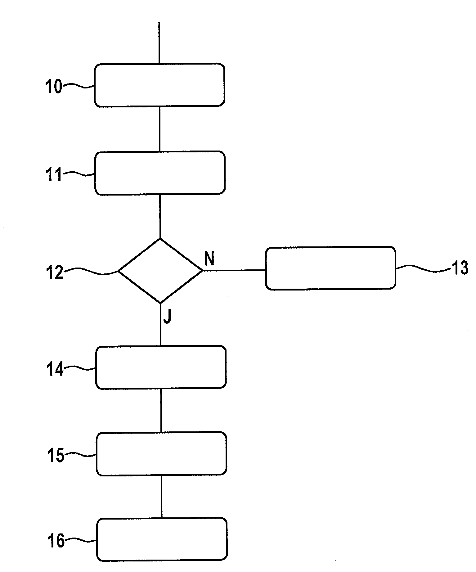
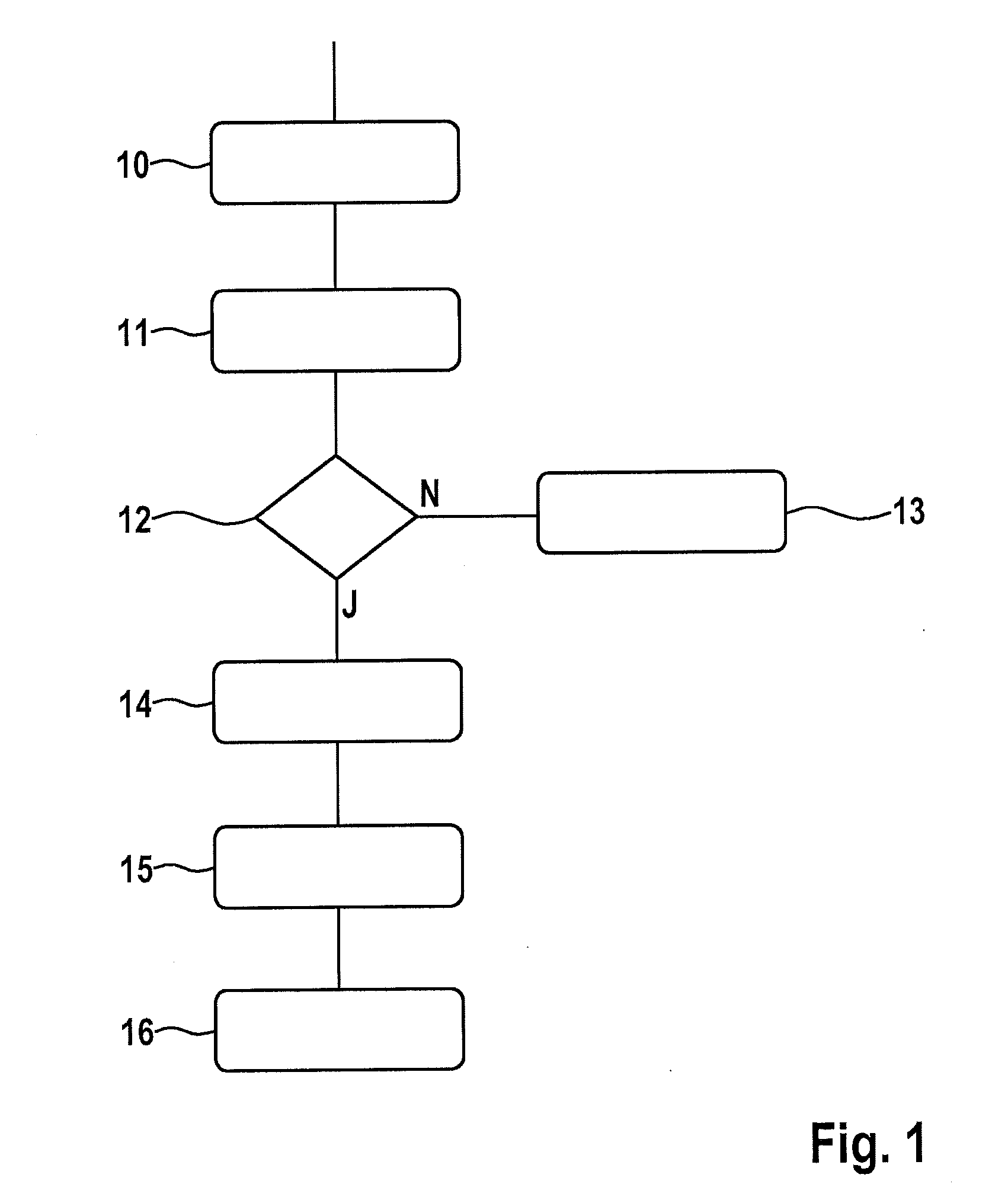
[0025]FIG. 1 shows a first flow chart of a first program sequence for determining learned values for monitoring the function of an exhaust-gas sensor implemented as wideband lambda oxygen sensor. The first program sequence is stored in a control unit (not shown) assigned to an internal combustion engine, the internal combustion engine constituting part of a hybrid drive.

[0026]In a first function block 10, the internal combustion engine is operated in trailing-throttle operation. The trailing throttle operation is not provided during regular operation of the internal combustion engine and is requested separately in order to implement a trailing-throttle adaptation of the wideband lambda oxygen sensor. In addition to the trailing-throttle adaptation, a first function control of the wideband lambda oxygen sensor in a second function block 11 takes place during the trailing-throttle operation which is suitable for the function control of wideband lambda oxygen sensors. In a first query ...


PUM


Abstract

A method for monitoring the function of an exhaust-gas sensor in the exhaust duct of an internal combustion engine. A first function control of the exhaust-gas sensor takes place in a first operating point of the internal combustion engine, and in the case of an intact exhaust-gas sensor, the output signal of the exhaust gas sensor or a characteristic quantity derived therefrom is determined in at least one second operating point of the internal combustion engine in the case of an intact exhaust-gas sensor and stored as learned value, and the monitoring of the function of the exhaust-gas sensor during a subsequent operation of the internal combustion engine in the second operating point takes place by comparing the output signal of the exhaust-gas sensor or the characteristic quantity derived therefrom, with the learned value. A corresponding device for implementing the method is also described.

Description

FIELD[0001]The present invention relates to a method for monitoring the function of an exhaust-gas sensor in the exhaust duct of an internal combustion engine.[0002]In addition, the present invention relates to a corresponding device for monitoring an exhaust-gas sensor in an exhaust duct of an internal combustion engine, which has a control unit, assigned to the internal combustion engine and the exhaust-gas sensor, for controlling the internal combustion engine and for analyzing the output signals of the exhaust-gas sensor.BACKGROUND INFORMATION[0003]Exhaust-gas sensors featuring various designs are currently used for monitoring the emissions of internal combustion engines. To ensure this function, the exhaust-gas sensors must be checked at regular intervals, e.g., within the framework of an on-board diagnosis (OBD), with regard to their proper functioning. Specific operating states of the internal combustion engine need to be present in order to implement a few of the diagnostic ...

Claims


Application Information

Patent Timeline
17 Oct 2013
Publication
US20130269316A1
IPC
F01N11/00
CPC
F01N11/00; F02D41/123; F02D41/1495; F02D41/2441; F02D41/2474
Inventors
STEINERT, THOMAS