
Hinge mechanism

A hinge mechanism and hinge seat technology, applied in mechanically driven excavators/dredgers, etc., can solve problems such as wear and tear, and achieve the effects of reducing wear, increasing bushings, and facilitating disassembly and maintenance.

Active Publication Date: 2013-02-27
LIUZHOU LIUGONG EXCAVATORS +2
View PDF4 Cites 9 Cited by
  • Summary
  • Abstract
  • Description
  • Claims
  • Application Information

AI Technical Summary

Problems solved by technology

[0003] The object of the present invention is to provide a method that can reduce the gap between the pin shaft and the two hinge parts in view of the shortcomings that the pin shaft is fixedly connected to one of the two hinge parts in the existing hinge mechanism and causes serious wear and tear between the pin shaft and the other part. worn hinge mechanism

Method used


Image

  • Hinge mechanism
  • Hinge mechanism
  • Hinge mechanism

Examples


Embodiment 2

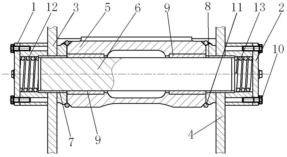
[0021] Such as figure 2 image 3 As shown, compared with the hinge mechanism in Embodiment 1, the difference is that in the hinge mechanism in this embodiment, a left return spring 12 and a right return spring 13 are arranged at both ends of the pin shaft 6, and the left return spring 12 The left end of the left return spring is contacted and connected with the left cover plate 1, the right end of the left return spring is in contact with the left end of the pin shaft 6 and the left end of the left bushing simultaneously, and the left end of the right return spring 13 is connected with the right end of the pin shaft 6 and the right end of the right bushing at the same time Contact connection, the right end is in contact with the right cover plate, that is, the left return spring 12 is limited between the left cover plate 1 and the left bushing 7, and the right return spring 13 is limited between the right cover plate 2 and the right bushing 8, Its maximum stroke is limited, so...


PUM


Abstract

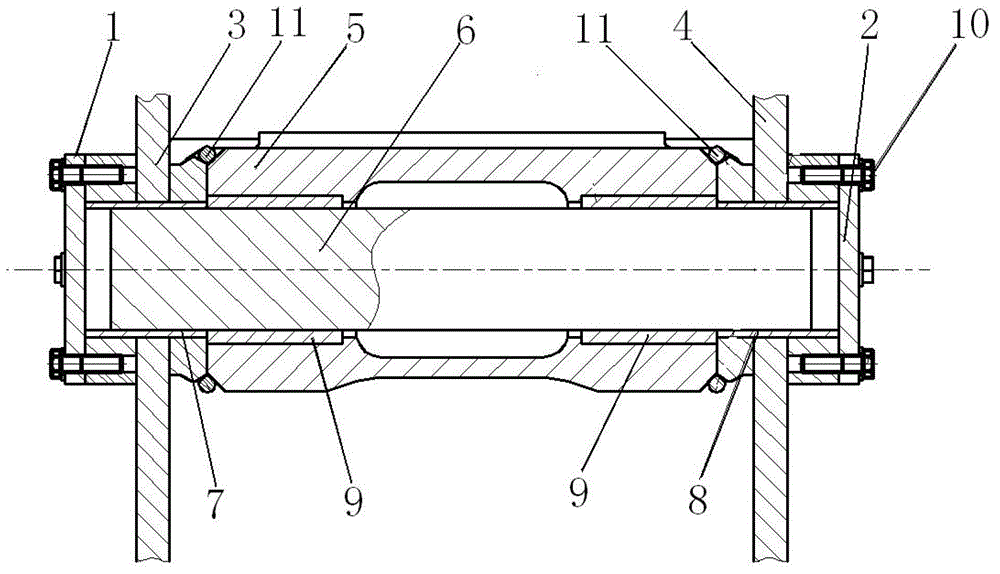
The invention relates to a hinge mechanism which aims at solving the defect that the existing hinge mechanism can be easily worn to be damaged. The hinge mechanism comprises a first hinging piece, a second hinging piece and a pin shaft, wherein the first hinging piece comprises a left hinging base and a right hinging base, a left circular hole and a right circular hole are respectively arranged on the left hinging base and the right hinging base, the second hinging piece is arranged between the left hinging base and the right hinging base, a middle circular hole is arranged on the second hinging piece, the left circular hole, the middle circular hole and the right circular hole are coaxially arranged with one another, a left lining, a middle lining and a right lining are in interference fit with the inner parts of the left hinging base, the middle circular hole and the right hinging base, the pin shaft penetrates through the inner holes of the left lining, the middle lining and the right lining, and is in clearance fit with the linings, and the opposite outer sides of the two hinge bases are respectively provided with a limit device preventing the pin shaft from axially falling out of the left lining and the right lining. In the hinge mechanism, the pin shaft is not fixed at any one of components, can freely and relatively rotate relative to the component which is small in rotation resistance, and can axially move left and right properly, so that the wear between the pin shaft and the lining can be reduced, and the service life of related parts can be prolonged. Meanwhile, the linings are added, so that the service life of the linings can be prolonged.

Description

technical field [0001] The invention relates to a connection structure, in particular to a hinged hinge mechanism. Background technique [0002] If the boom, arm, bucket and platform of the excavator working device are to be connected together and can rotate freely, it must be connected by a hinge mechanism; at present, the hinge mechanism of most excavator working devices is as follows: two There is a round hole on each of the individual components and the pin shaft is connected together, one of the components is fixed with the pin shaft, and the relative rotation between this component and the pin shaft does not occur, and the other component and the pin shaft must have relative rotation. , the pin shaft of this hinge mechanism cannot independently choose which member to rotate with respect to, and the pin shaft cannot move in a short distance in the axial direction. For example: the bucket and the pin shaft are fixed together by assembly, the pin shaft also rotates when ...

Claims


Application Information

Patent Timeline
IPC IPC(8): E02F3/36E02F3/38
Inventor 李玉广林明智唐建国骆间芳
Owner LIUZHOU LIUGONG EXCAVATORS
Learn More