Reamer

A reamer and expander technology, which is applied to earth-moving drilling, drill bits, drilling equipment, etc., can solve the problems of large limitations, affecting the flexibility of the blade, and easy access.

Active Publication Date: 2013-02-27
BC P INC CHINA NAT PETROLEUM CORP +1
View PDF8 Cites 5 Cited by
  • Summary
  • Abstract
  • Description
  • Claims
  • Application Information

AI Technical Summary

Problems solved by technology

[0004] The above-mentioned prior art can complete specific hole reaming tasks, but there are still the following deficiencies: 1. During the drilling process, the expansion and contraction of the reaming blades can easily cause drilling fluid to easily enter the joint parts of the reaming body, affecting the flexibility of the blades The reamer of the fixed wing is limited by the wall thickness of the tool body, so the size of the reamer is small, and it can exp

Method used


Image

  • Reamer
  • Reamer
  • Reamer

Examples


Embodiment 1

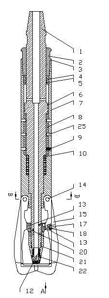
[0051] An eye reamer, including an outer cylinder 7 and a blade mechanism, and also includes a transmission shaft mechanism arranged in the outer cylinder 7 and sliding axially along the outer cylinder 7, and a reset mechanism for resetting the transmission shaft mechanism. The upper end of the outer cylinder 7 is A first sealing structure that cooperates with the outer wall of the transmission shaft mechanism to seal is provided, a blade groove 26 is provided at the lower end, a second sealing structure is provided at the end of the outer cylinder 7, the blade mechanism is arranged in the blade groove 26, and the transmission shaft mechanism An expander that drives the blade mechanism to expand outward is arranged on the top, and the inner cavity of the transmission shaft mechanism communicates with the blade groove 26 .

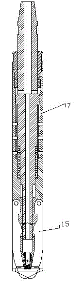
[0052] In the present invention, the blade mechanism includes a main blade 15 and an auxiliary blade 16, the main blade 15 is two with the same structure, a...

Embodiment 2

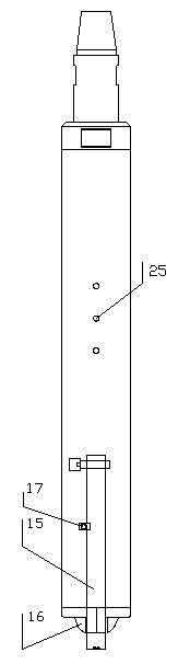
[0068]The outer cylinder 7 is a cylindrical structure, and the lower end of the cylinder has a blade groove 26 and a blade pin hole 27 connecting the main blade 15 and the auxiliary blade 16, and the main blade 15 and the auxiliary blade 16 are connected by the blade pin hole 27. In the blade groove 26, the rear end of the outer cylinder 7 has an end cap groove 28, and the assembled end cap 2 is arranged in the end cap groove 28, and a fixed sleeve 4 is arranged at the front end of the end cap 2, between the fixed sleeve 4 and the A fixed sleeve sealing ring 5 is arranged between the transmission shafts 1; a pin hole 25 and a spring groove 24 are arranged in the middle section of the outer cylinder 7. After assembling the present invention, the outer cylinder 7 and the fixed sliding sleeve 8 are fixed by the connecting pin 9 through the pin hole 25 The lower end of the transmission shaft 1, namely the reaming end, is provided with a cam groove 30 and a runner 29, the cam groove...

Embodiment 3

[0072] The assembly sequence of the present invention is:

[0073] Install the return spring 10 in the direction of the inner thread of the outer cylinder 7, and then put in the fixed sliding sleeve 8. The fixed sliding sleeve 8 is in the shape of an outer circle and an inner octagonal shape. The outer octagonal structure of the fixed shaft 11 matches the inner octagonal structure of the fixed sliding sleeve 8. Install the outer cylinder seal ring 6 on the transmission shaft 1, after the fixed sleeve seal ring 5 is installed on the fixed sleeve 4, the transmission shaft 1 is put into the outer cylinder 7 from the direction of the inner thread of the outer cylinder 7, and on the end surface of the inner thread of the outer cylinder 7 Place gasket 3, then put into end cap 2, end cap 2 is threadedly connected with outer cylinder 7, then put connecting pin 9 into pin hole 25.

[0074] Four cam blocks 13 are respectively installed in the cam grooves 30 on the four faces of the lowe...


PUM


Abstract

The invention discloses a reamer. The reamer comprises an outer cylinder, a blade mechanism, a transmission shaft mechanism and a reset mechanism, wherein the transmission shaft mechanism is arranged in the outer cylinder and axially slides along the outer cylinder, and the reset mechanism is used for resetting the transmission shaft mechanism; a first sealing structure matched and sealed with the outer wall of the transmission shaft mechanism is arranged at the upper end of the outer cylinder, a blade groove is formed in the lower end of the outer cylinder, a second sealing structure is arranged at the end part of the outer cylinder, and the blade mechanism is arranged in the blade groove; and an expander for driving the blade mechanism to expand outwards is arranged on the transmission shaft mechanism, and the inner cavity of the transmission shaft mechanism is communicated with the blade groove. The reamer has contractility and cannot be limited by the wall thickness of a tool body, the reaming size is large, and meanwhile, the sealing structure is reasonable; and in the drilling process, the drilling fluid hardly enters key components of the reamer in the processes of expansion and contraction of a reaming blade, and the flexibility of the blade cannot be influenced.

Description

technical field [0001] The invention relates to a downhole reaming tool for drilling, in particular to a reamer for reaming operations in the drilling process, which is used in oil and gas drilling technology and belongs to the technical field of design and manufacture of downhole tools. Background technique [0002] In the process of oil and gas drilling operations, for the convenience of running casing, or when drilling into formations that are easy to shrink in diameter, the drilled wellbore often has different degrees of diameter reduction. In this case, it is necessary to The borehole is enlarged to a larger diameter borehole. As oil and gas drilling shifts to deep wells, ultra-deep wells, and high-pressure oil and gas wells, drilling is facing more and more problems. As an important means to deal with drilling abnormalities, hole reaming technology is also developing continuously. It can not only be used as a simple tool to expand the wellbore, but also can be used as...

Claims


Application Information

Patent Timeline
IPC IPC(8): E21B10/32
Inventor 陈立刘彬徐文何超胡畔邓元洲
Owner BC P INC CHINA NAT PETROLEUM CORP
Why Eureka
Try Eureka