Refrigerator

A technology for refrigerators and outer boxes, applied in the field of refrigerators, can solve the problems of increasing the amount of vacuum insulation materials, increasing the amount of heat intrusion, and limiting the volume of vacuum insulation materials, and achieving the effect of reducing intrusion heat

Active Publication Date: 2013-02-27
MITSUBISHI ELECTRIC CORP
View PDF4 Cites 1 Cited by
  • Summary
  • Abstract
  • Description
  • Claims
  • Application Information

AI Technical Summary

Problems solved by technology

[0003] The insulation performance of refrigerators in recent years has been greatly improved by installing vacuum insulation materials in refrigerators. Since vacuum insulation materials are installed in rigid urethane foam, the volume that can be installed with vacuum insulation materials is limited and it is difficult to increase Dramatically increase the amount of vacuum insulation
[0004] In addition, it is difficult to secure a sufficient volume to cover the vacuum insulation material at both ends of the outer shell including the outer box and the inner box, and to have a complex shape, and it is difficult to greatly increase the amount of the vacuum insulation material.
[0005] In addition, even if a vacuum insulation material is mounted in a refrigerator in which the outer box is formed of a metal plate, the heat flow of the flange formed by bending the outer box increases due to the influence of the thermal bridge generated by the metal plate, thereby When heated, the amount of heat intrusion into the refrigerator increases

Method used


Image

  • Refrigerator
  • Refrigerator
  • Refrigerator

Examples


Embodiment approach 1

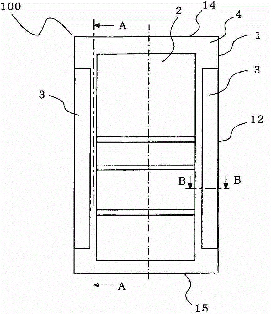
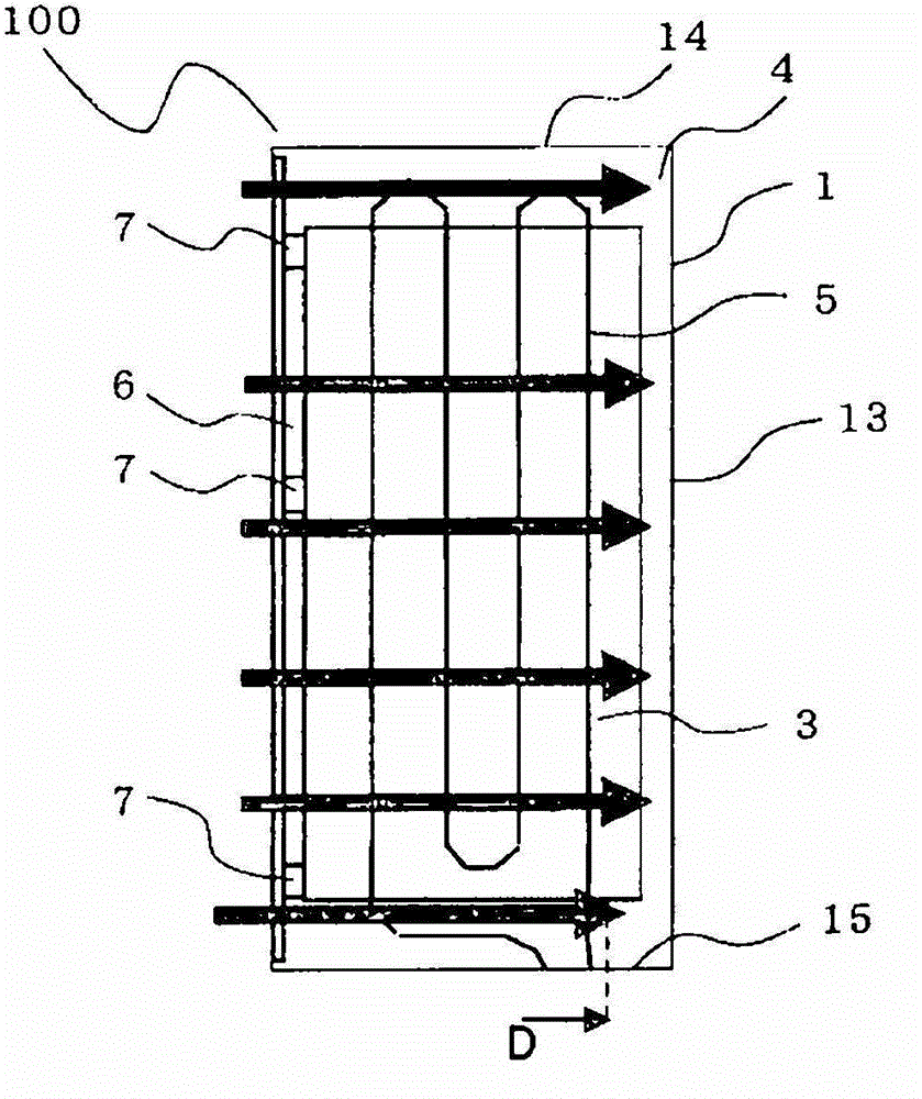
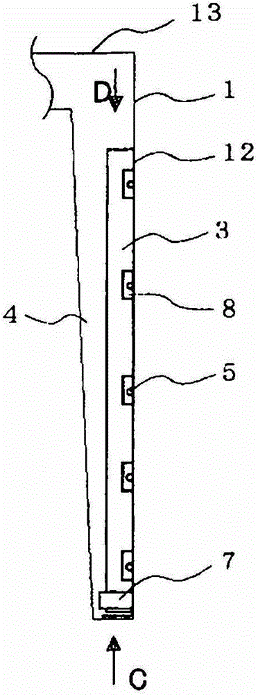
[0031] figure 1 It shows a front cross-sectional view of refrigerator 100 in Embodiment 1 of the present invention. figure 2 express figure 1 A-A sectional view of . image 3 express figure 1 BB sectional view of . Figure 4 It is a schematic explanatory drawing showing the positional relationship of the vacuum heat insulating material 3, the cushioning material 7, and each flange part in Embodiment 1 of this invention. and, Figure 4 for zoomed in image 3 A diagram of the front of the .

[0032] Next, use Figure 1 to Figure 4 The configuration of refrigerator 100 will be described.

[0033] figure 1 The refrigerator 100 is configured by fitting an outer box 1 made of metal such as iron and an inner box 2 made of synthetic resin such as ABS. The side surface 12 of the outer box 1 is provided on the side of the refrigerator 100 , the top surface 14 of the outer box 1 is provided on the upper surface of the refrigerator 100 , and the bottom surface 15 of the outer...

Embodiment approach 2

[0057] Next, use Figure 8 Embodiment 2 of the present invention will be described. In addition, in Embodiment 2, items that are not particularly described are the same as in Embodiment 1, and the same functions and configurations will be described using the same symbols.

[0058] Figure 8 It is a schematic explanatory drawing which shows the positional relationship of the vacuum heat insulating material 3 and each flange part in Embodiment 2 of this invention.

[0059] After forming the fitting recessed part 18a, the back flange 18 is bent 180 degrees, and is extended toward the outer case 1 direction. The vicinity of the bent portion of the back flange 18 is in close contact with the vacuum insulation material 3 . The front end portion 18b of the extended portion of the rear flange 18 toward the outer box 1 is located in front of the refrigerator 100 in the front-rear direction of the refrigerator 100 compared to the position in contact with the vacuum insulation materia...


PUM


Abstract

The invention provides a refrigerator capable of reducing the heat energy intruding into the refrigerator. The refrigerator is provided with a front surface flange (17), a back surface flange (18), an inner case flange (19), and a buffer material (7). The front surface flange (17) is integratedly connected with a front edge of an outer case (1), and is formed by being bent towards an inner side. The back surface flange (18) is integratedly connected with the front surface flange (17), and is formed on a back surface side of the front surface flange (17), and also can be bent together with the front surface flange (17) to form an embedded concave part (18a), then can be extended towards the depth direction of the refrigerator. The inner case flange (19) is integratedly connected with the front edge part of the inner case (2), and can be bent outwards, and then is clamped with the embedded concave part (18a) to fix the outer case (1) and the inner case (2). The buffer material (7) is disposed between the front side of the refrigerator (100) of the vacuum heat insulation material (3) and the back surface flange (18).

Description

technical field [0001] The present invention relates to a refrigerator using a vacuum heat insulating material. Background technique [0002] In recent years, there has been an increasing demand for energy-saving refrigerators, and many refrigerators have been equipped with vacuum insulation materials that are far superior in insulation performance to rigid urethane foam. [0003] The insulation performance of refrigerators in recent years has been greatly improved by installing vacuum insulation materials in refrigerators. Since vacuum insulation materials are installed in rigid urethane foam, the volume that can be installed with vacuum insulation materials is limited and it is difficult to expand Increase the amount of vacuum insulation material drastically. [0004] In addition, it is difficult to secure a sufficient volume to cover the vacuum insulation material at both ends of the outer shell including the outer box and the inner box, and to have a complex shape, and ...

Claims


Application Information

Patent Timeline
Patent Type & Authority Applications(China)
IPC IPC(8): F25D23/06
Inventor 中津哲史桥谷直树
Owner MITSUBISHI ELECTRIC CORP
Why Eureka
Try Eureka