
Sub-aperture polarization imaging system

A polarization imaging and aperture-division technology, which is applied in the field of photoelectric detection, can solve the problems of bulky, incapable of imaging, and high cost, and achieve the effect of improving imaging quality and making up for the loss of energy.

Inactive Publication Date: 2013-02-27
BEIJING INSTITUTE OF TECHNOLOGYGY
View PDF6 Cites 21 Cited by
  • Summary
  • Abstract
  • Description
  • Claims
  • Application Information

AI Technical Summary

Problems solved by technology

[0003] The method based on time-sharing is simple and easy to implement, but at the cost of loss of time resolution, it cannot image changing scenes or moving targets, the real-time performance is poor, and there are registration problems of multi-polarization images
The method based on wavefront beam splitting solves the problem of multi-polarization real-time imaging, but due to the multi-optical path and multi-detector structure, the system is bulky, inconvenient to install and adjust, and expensive
The third type of polarization imaging device has made great technological progress compared with the first two, but because the device uses 4 lenses to directly image the 4 polarized lights corresponding to it, since the optical axes of the 4 lenses are not on the same straight line , the imaging quality is very poor when receiving with the same large area array CCD, and it is very likely that the overlapping of image planes will occur

Method used


Image

  • Sub-aperture polarization imaging system
  • Sub-aperture polarization imaging system
  • Sub-aperture polarization imaging system

Examples


Embodiment Construction

[0041] The present invention will be described in detail below with reference to the accompanying drawings and examples.

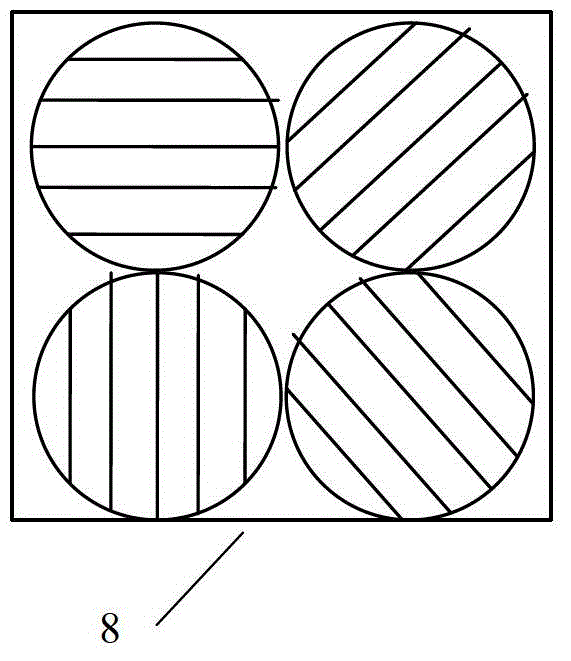
[0042] The present invention provides a sub-aperture polarization imaging system. In order to make up for the poor imaging quality caused by the direct imaging of polarized light by four lenses in the prior art, it is considered to use a negative lens and a positive lens in the system to solve the problem. problem, the negative lens is used to eliminate field curvature in the system, and the positive lens eliminates spherical aberration and coma. In order to better eliminate spherical aberration and coma, consider using multiple lenses to combine into a positive lens, but considering Light transmittance, processing cost and ease of processing determine the use of a combination of a positive lens and a meniscus lens to achieve the above objectives.

[0043] Because the direct projection imaging of the 4 lenses in the sub-lens array 9 can cause image overlap...


PUM


Abstract

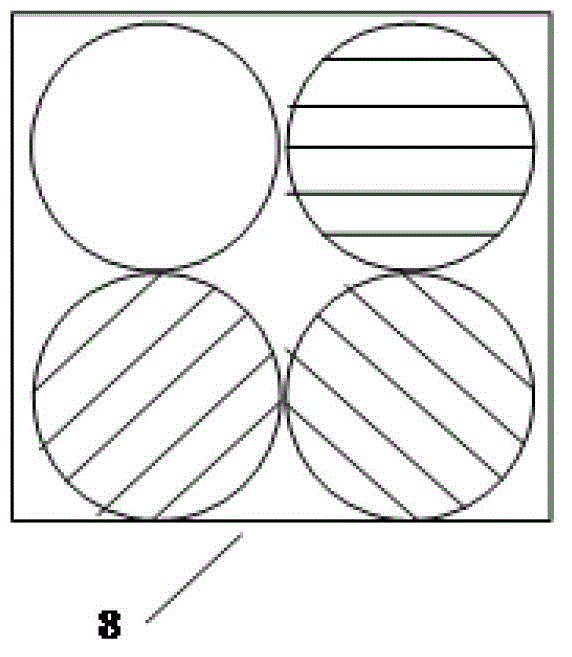
The invention discloses a sub-aperture polarization imaging system. The sub-aperture polarization imaging system comprises a telephoto objective, an optical filter, a field stop, a field lens, a collimation module, an aperture dividing module, a focusing imaging module and a charge coupled device (CCD) detector which are coaxially arranged in the incident light spreading direction. The sub-aperture polarization imaging system achieves sub-aperture polarization imaging by aid of an optical imaging system, removes spherical aberration and comatic aberration by aid of the correction field curvature of the focusing imaging module, and accordingly improves imaging quality and prevents the image surfaces from being overlapped. When the imaging environment is dark, three linear polaroids with different polarization angles (0 degree, 60 degrees and 120 degrees respectively) can be placed in a polarization array, and the remained aperture is used for non-polarization imaging. According to the sub-aperture polarization imaging system, the influence of imaging illumination is considered on the condition of not changing the system structure, and accordingly energy loss of light caused by the polaroids is made up.

Description

technical field [0001] The invention relates to the technical field of photoelectric detection, in particular to a sub-aperture polarization imaging system. Background technique [0002] There are mainly three existing polarization imaging methods. One is based on time-sharing imaging technology. In this method, the polarizer is fixed in front of the imaging system, and different polarization states are obtained by manually or electrically rotating the polarizer to different linear polarization directions. The other is an imaging technology based on wavefront beam splitting. This method uses a beam splitter to split the target beam into multiple beams, and uses multiple polarizers and multiple detectors to image the same scene in real time. Usually, each A detector measures a polarization state of the scene; the third is a real-time small polarization imaging device disclosed in the application number 200910237178.7, which includes a lens array, a polarizer array and a large...

Claims


Application Information

Patent Timeline
Patent Type & Authority Applications(China)
IPC IPC(8): G02B27/28G02B27/00
Inventor 王霞陈振跃马斌金伟其
Owner BEIJING INSTITUTE OF TECHNOLOGYGY
Learn More