
Displacement drive device based on interaction between permanent magnet and electromagnet

A driving device and interaction force technology, applied in the direction of electromechanical devices, electric components, electrical components, etc., can solve the problems of unsuitable expansion and contraction mechanisms, many driving and excitation links, and many components, so as to achieve large driving force and direct motion driving , The effect of precise driving displacement

Active Publication Date: 2016-12-21
SHANGHAI JIAOTONG UNIV
View PDF5 Cites 0 Cited by
  • Summary
  • Abstract
  • Description
  • Claims
  • Application Information

AI Technical Summary

Problems solved by technology

[0002] In recent years, the field of electric and magnetostrictive materials has developed rapidly, and new sensitive materials such as giant magnetostrictive materials, piezoelectric ceramics and magnetostrictive shape memory alloys have been produced, which can be used in the development of precision drives, sensors and linear motors. The material has the advantages of high energy density, high output power, and precise expansion and deformation. However, the drive based on smart materials generally has disadvantages such as small motion displacement, many drive excitation links, many components, and poor reliability.
Therefore, telescopic mechanisms based on smart materials are not suitable for small-volume, high-energy, and large-stroke drive applications

Method used


Image

  • Displacement drive device based on interaction between permanent magnet and electromagnet
  • Displacement drive device based on interaction between permanent magnet and electromagnet
  • Displacement drive device based on interaction between permanent magnet and electromagnet

Examples


Embodiment 1

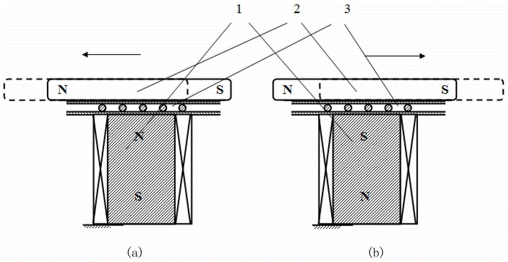
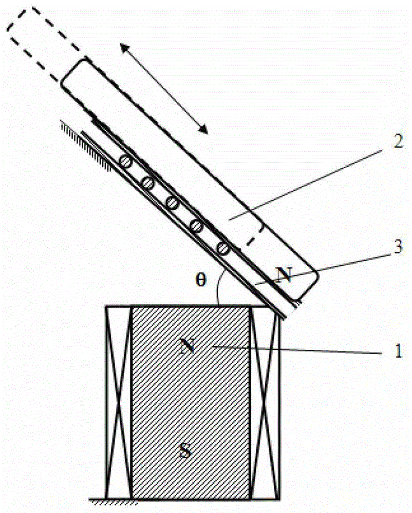
[0038] This embodiment includes: a driving part 1 and a motion-activating part 2 that generate an interaction force, and a guide part 3 arranged between the driving part 1 and the motion-activating part 2 for constraining the displacement direction of the motion-activating part 2 .

[0039] Such as figure 1 As shown, in the present embodiment, the above-mentioned driving part 1 is a fixed electromagnet, and the above-mentioned motion starting part 2 is a moving permanent magnet. Initially, the fixed electromagnet is placed vertically to generate vertical magnetic poles; the moving permanent magnet is placed horizontally to generate horizontal permanent magnetic poles, and is installed on one pole surface of the fixed electromagnet and the side of the moving permanent magnet There are guide parts 3 placed horizontally. The guide part 3 includes a stator and a mover, wherein the stator is fixedly connected to the end face of the fixed electromagnet, and the mover is fixedly con...

Embodiment 2

[0044] Embodiment 2 is a modification example of Embodiment 1.

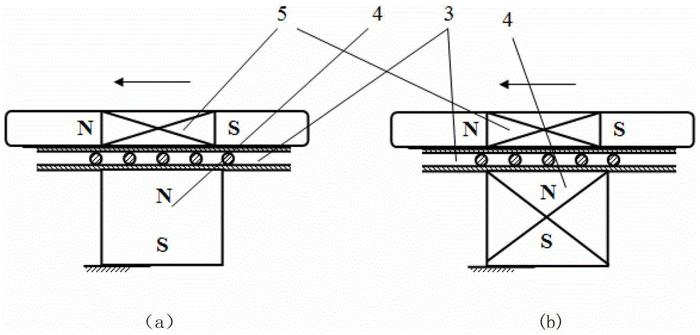
[0045] Such as figure 2 Shown in (a), on the basis of embodiment 1, the present embodiment differs from embodiment 1 in that the motion starting part 2 is replaced with a moving electromagnet, and the drive part 1 is replaced with a fixed permanent magnet.

Embodiment 3

[0047] Embodiment 3 is a modification example of Embodiment 1.

[0048] Such as figure 2 Shown in (b), on the basis of embodiment 1, the present embodiment differs from embodiment 1 in that the motion starting part 2 is replaced with a moving electromagnet, and the driving part 1 is still a fixed electromagnet, and the applied magnetic field The acting forces are all electromagnetic field forces.


PUM


Abstract

The invention discloses a shift driving device and a combination thereof based on the interaction of a permanent magnet and an electromagnet. The device comprises a driving component, a motion initiating component and a guide component, wherein the driving component and the motion initiating component interacts with each other, the guide component is arranged between the driving component and the motion initiating component for restricting the shift direction of the motion initiating component, a fixed electromagnet or a fixed permanent magnet is used as the driving component, and a mobile permanent magnet or a mobile electromagnet is used as the motion initiating component. The device has the advantages of direct motion driving, simple mechanism, great rigidity, accurate driving shift, simplicity and convenience in control, rapid driving response and high efficiency. Linear reciprocating translational motion or rotating motion is directly generated based on the displacement of magnetic poles. Large stroke and micro stroke are easily realized. Motion force, shift distance and shift accuracy can be controlled through the accurate application of a magnetic field or the intensity of current. The magnetic field is directly used for driving, and a larger driving magnetic field is produced under the combined action of an electromagnetic field and a permanent magnetic field, so that the mechanism has larger driving force.

Description

technical field [0001] The invention relates to the field of translation / rotation drive technology, in particular to a displacement drive device based on the interaction between permanent magnets and electromagnets. Background technique [0002] In recent years, the field of electric and magnetostrictive materials has developed rapidly, and new sensitive materials such as giant magnetostrictive materials, piezoelectric ceramics and magnetostrictive shape memory alloys have been produced, which can be used in the development of precision drives, sensors and linear motors. Materials have the advantages of high energy density, high output power, and precise stretching and deformation. However, the drives based on smart materials generally have disadvantages such as small motion displacement, many driving excitation links, many components, and poor reliability. Therefore, telescopic mechanisms based on smart materials are not suitable for small-volume, high-energy, and large-str...

Claims


Application Information

Patent Timeline
Patent Type & Authority Patents(China)
IPC IPC(8): H02K7/06
CPCH02K7/06
Inventor 杨斌堂
Owner SHANGHAI JIAOTONG UNIV
Learn More