
Tool for motor rotor into shaft

A technology of motor rotor and tooling, applied in the direction of manufacturing stator/rotor body, etc., can solve the problems of cast aluminum rotor radial runout exceeding the error, the force deformation of the cast aluminum shaft, and the unbalanced rotation of the cast aluminum rotor.

Inactive Publication Date: 2013-02-27
NINGBO WOLI TECH CO LTD
View PDF7 Cites 1 Cited by
  • Summary
  • Abstract
  • Description
  • Claims
  • Application Information

AI Technical Summary

Problems solved by technology

[0002] In order to ensure the firm combination of the motor mandrel and the cast aluminum rotor, in the current assembly process, the cast aluminum rotor of the motor is generally pressed into the mandrel by interference fit. However, due to a certain amount of interference, it is not known when pressing How much pressure, when press-fitting, if the pressure provided is too small, the cast aluminum rotor cannot be pressed into the mandrel. Error requirements, unbalanced rotation of the cast aluminum rotor, and defects such as excessive noise caused by the unbalanced rotation of the cast aluminum rotor will also damage the structure of the cast aluminum rotor due to excessive deformation and shorten the service life of the cast aluminum rotor

Method used


Image

  • Tool for motor rotor into shaft
  • Tool for motor rotor into shaft
  • Tool for motor rotor into shaft

Examples


Embodiment 1

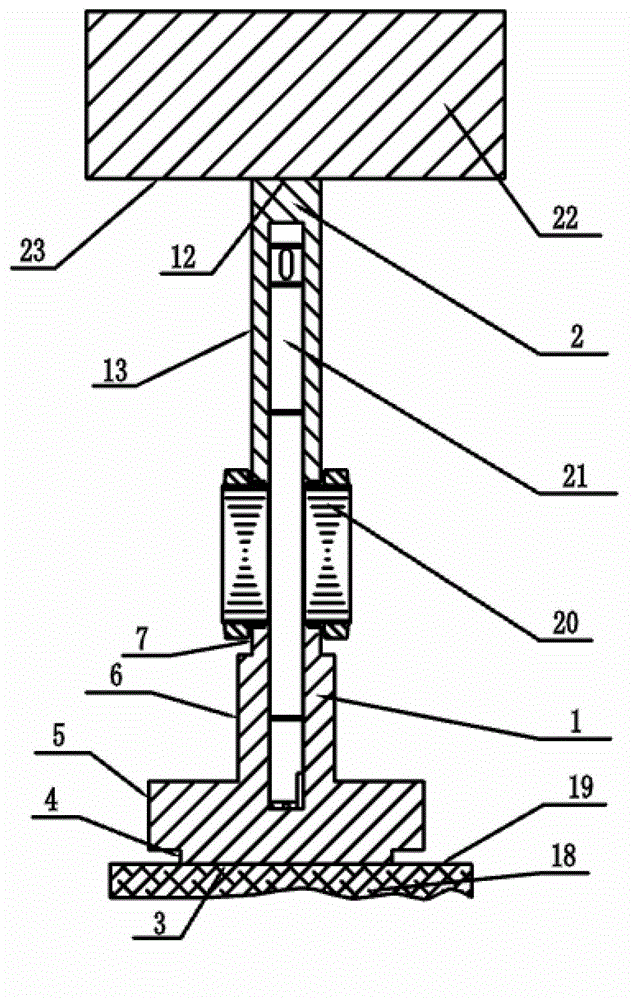
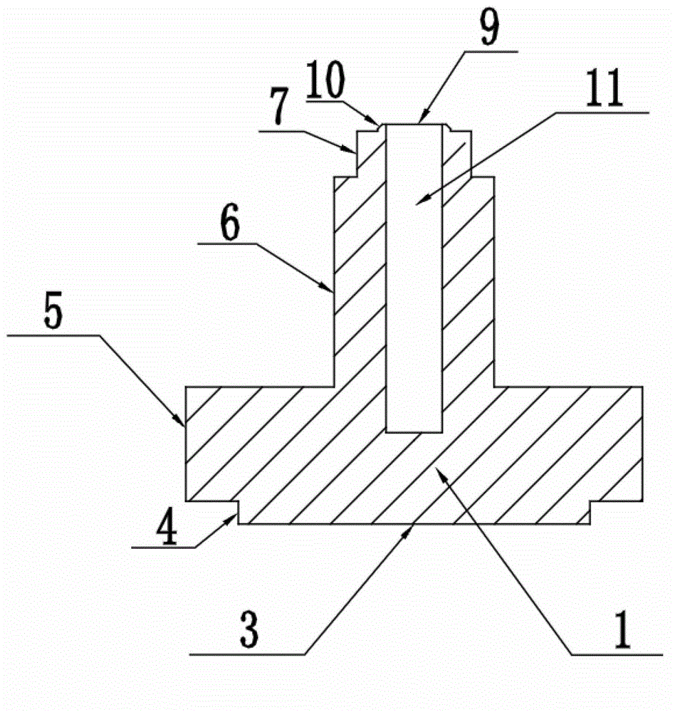
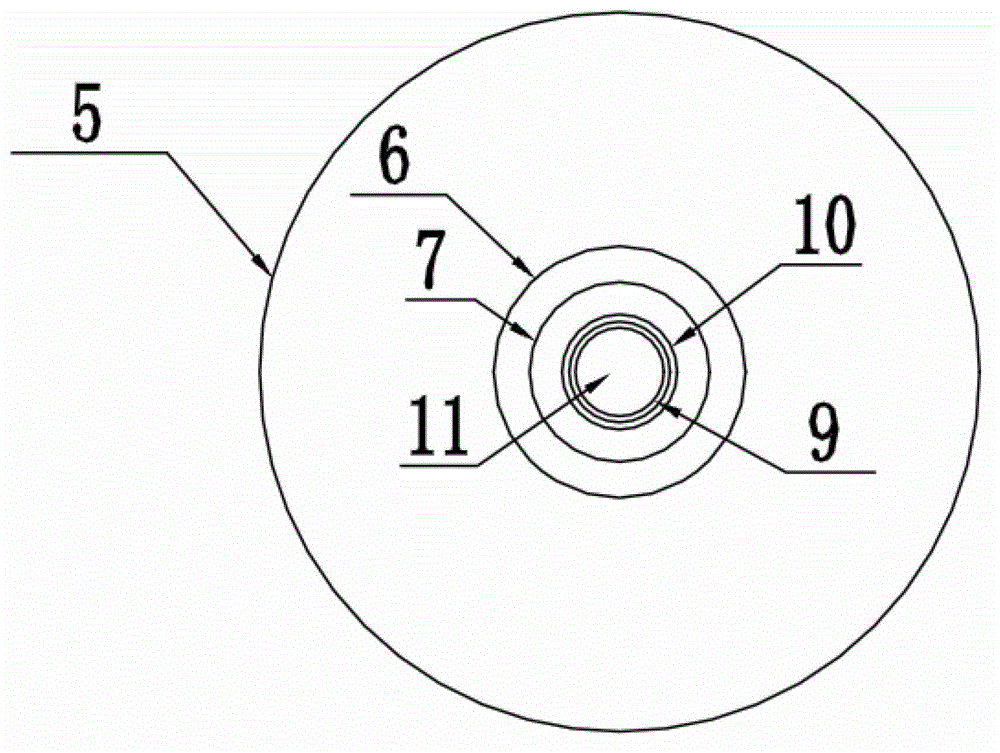
[0024] First, place the lower chassis 1 of the tooling on the flat upper surface III19 of the workbench 18, insert one end of the mandrel 21 into the central cylindrical hole I11 of the lower chassis 1 of the tooling, and ensure that the mandrel 21 and the central cylindrical hole I 11 The end surface of the connected end is in contact with the bottom end surface of the central cylindrical hole I 11, and penetrates the cast aluminum rotor 20 from the other end of the mandrel 21, so that the cast aluminum rotor 20 is connected with the mandrel 21 through the center hole, and under the action of its own gravity, the cast aluminum rotor 20 The lower end surface of the aluminum rotor 20 is kept in contact with the flat upper surface I9 of the boss I10, and the tooling upper sleeve 2 is inserted into the other end of the mandrel 21 through the central cylindrical hole II14. Under the action of its own gravity, the boss II15 The flat lower end surface II 16 is kept in contact with th...


PUM


Abstract

The invention relates to a tool for a motor rotor into a shaft, which comprises a lower tool chassis and an upper tool sleeve, wherein the lower tool chassis comprises a plurality of cylinders, i.e., a cylinder I, a cylinder II, a cylinder III and a cylinder IV, which are connected, the upper end surface of the cylinder I is connected with the lower end surface of the cylinder II, the upper end surface of the cylinder II is connected with the lower end surface of the cylinder III, the upper end surface of the cylinder III is connected with the lower end surface of the cylinder IV, the axes of the cylinder I, the cylinder II, the cylinder III and the cylinder IV are coincided, a boss I is arranged at the center of the upper end surface of the cylinder IV along the direction of the central axis, the upper tool sleeve is formed by a cylinder V, and a boss II is arranged at the center of the lower end surface of the cylinder V along the direction of the central axis. The tool disclosed by the invention is reasonable in design, compact in structure and high in hardness, can avoid the deformation of the rotor, and simultaneously avoids the conditions that due to the deformation of the rotor, the rotor is large in radial jumping and unbalanced in rotation, and the overhigh noise can be generated due to the unbalance in rotation of the rotor can be avoided.

Description

technical field [0001] The invention relates to the field of motor rotor press-fit assembly technology, in particular to a motor rotor shaft insertion tool. Background technique [0002] In order to ensure the firm combination of the motor mandrel and the cast aluminum rotor, in the current assembly process, the cast aluminum rotor of the motor is generally pressed into the mandrel by interference fit. However, due to a certain amount of interference, it is not known when pressing How much pressure, when press-fitting, if the pressure provided is too small, the cast aluminum rotor cannot be pressed into the mandrel. Error requirements, unbalanced rotation of the cast aluminum rotor, and defects such as excessive noise caused by the unbalanced rotation of the cast aluminum rotor will also damage the structure of the cast aluminum rotor due to excessive deformation and shorten the service life of the cast aluminum rotor. Contents of the invention [0003] The technical prob...

Claims


Application Information

Patent Timeline
Patent Type & Authority Applications(China)
IPC IPC(8): H02K15/02
Inventor 王伟刚倪国明
Owner NINGBO WOLI TECH CO LTD
Learn More