
Device and method for the heating and/or temperature control of prosthesis sockets

A device, prosthetic technology, applied in the field of devices and methods for heating and/or temperature control of prosthetic sockets, capable of solving problems such as intolerance

Inactive Publication Date: 2013-02-27
安德烈·马塞尔·埃米尔·阿勒芒
View PDF4 Cites 4 Cited by
  • Summary
  • Abstract
  • Description
  • Claims
  • Application Information

AI Technical Summary

Problems solved by technology

This method can be used for temporary pain relief, but only for amputated stumps where no orthopedic devices (such as prostheses) have been inserted, in which case the patient will not be able to tolerate this method because of friction and fulcrums

Method used


Image

  • Device and method for the heating and/or temperature control of prosthesis sockets
  • Device and method for the heating and/or temperature control of prosthesis sockets
  • Device and method for the heating and/or temperature control of prosthesis sockets

Examples


Embodiment approach

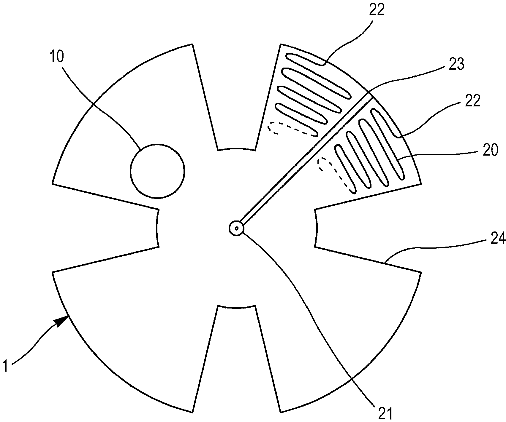
[0066] - the traces or heating body 20 can be manufactured by various processes, for example, screen printing;

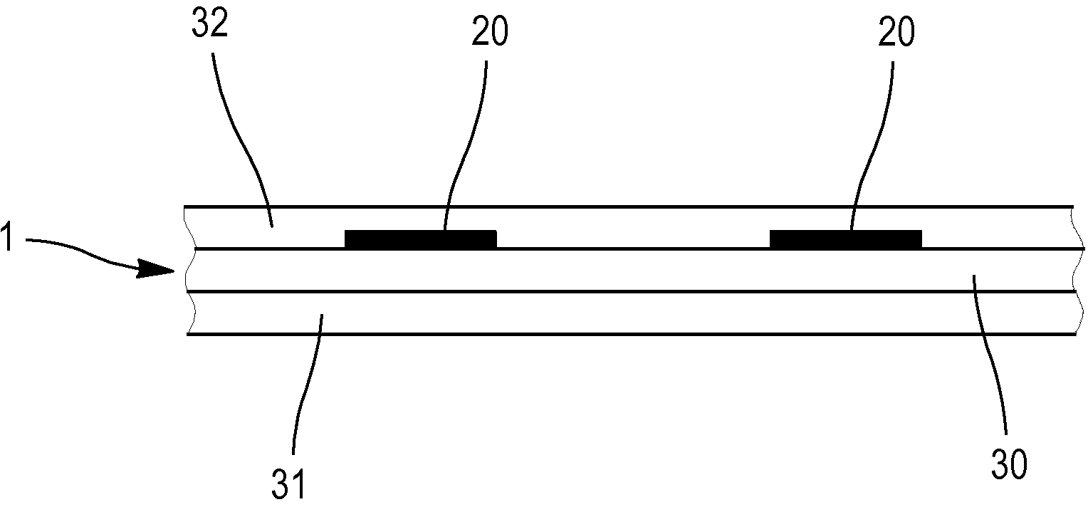
[0067] - the heating element 1 may comprise a support 30 molded according to a particular shape, for example, to best fit the shape of a particular surface;

[0068] - the heating element 1 can have any shape and can comprise any type of cutouts, depending on the prosthesis in which it is used;

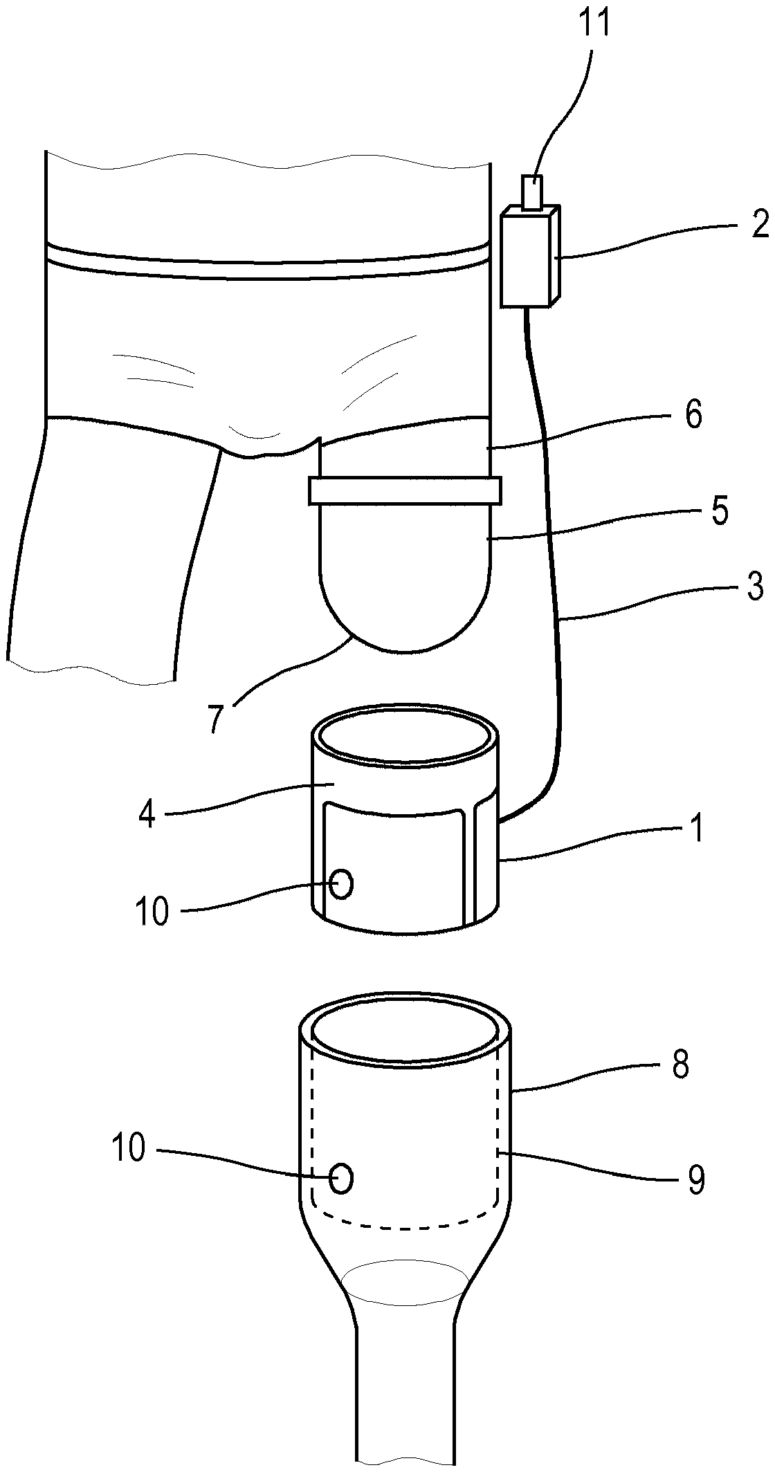
[0069] - The heating element 1 can be integrated into a part of the prosthesis during its manufacture, eg the flexible socket 4 or the rigid socket 9 or the main body 8, in particular by incorporating the heating element into this part.


PUM


Abstract

The invention relates to a device for heating and / or controlling the temperature of the socket of an orthopaedic appliance, which receives the distal end of an amputation stump, said device comprising a heating element arranged in the prosthetic appliance such that the parts of the socket in contact with the distal end of the amputation stump are heated and / or maintained at a predetermined temperature. The invention also relates to a method for improving the wearing comfort of an orthopaedic appliance, and to an orthopaedic appliance.

Description

technical field [0001] The present invention relates to an apparatus and method for heating and / or temperature control of sockets of orthopedic appliances for fitting amputee stumps. [0002] The technical field of the invention is that of orthopedics and prosthetics for amputees. Background technique [0003] Amputee patients often suffer from recurrent pain, also known as phantom limb pain, which is very distressing for amputee patients. [0004] As described in the paper by H.Flor, N.Birbaumer and R.A.Sherman ("Phantom LimbPain", Pain: Clinical Updates, Volume VIII, No 3, June 2000), these pains originate from the nerve endings of the stump, which The stump is the area of ​​the limb that has been amputated and is sensitive to stimuli (such as those associated with stump movement in prosthetics and friction) and cold temperatures. [0005] In this paper, it is also described that these painful conditions are often associated with a reduction in the velocity of the superf...

Claims


Application Information

Patent Timeline
Patent Type & Authority Applications(China)
IPC IPC(8): A61F2/78A61F2/80A61F7/00A61F2/70A61F2/76
CPCA61F2007/008A61F2007/0086A61F2007/0071A61F2002/7665A61F7/007A61F2/80A61F2/78A61F2/70A61F2007/0051A61F2/7812
Inventor 安德烈·马塞尔·埃米尔·阿勒芒
Owner 安德烈·马塞尔·埃米尔·阿勒芒
Learn More