Locking structure of needle barrel and core rod of safety syringe with retractable needle point

A technology for safe syringes and syringes, applied in the direction of syringes, hypodermic injection devices, infusion sets, etc., can solve the problems of reducing the assembly efficiency of the core rod and the syringe, increasing the manufacturing cost, and complicating the assembly, so as to achieve a fast and convenient assembly process , Reduce accessories, simplify the effect of assembly steps

Active Publication Date: 2015-10-21
CAINA TECH CO LTD
View PDF4 Cites 0 Cited by
  • Summary
  • Abstract
  • Description
  • Claims
  • Application Information

AI Technical Summary

Problems solved by technology

[0004]The above structural settings, although it can well realize the clamping and locking of the core rod after retraction, but due to the structural design defects, the core rod During the assembly process with the syringe, the two engaging flanges on the core rod cannot directly go over the engaging convex ring on the syringe for direct assembly, it must be completed with the help of a set of rings, where the rings can be set separately and movable The outer sides of the two engaging flanges on the core rod can also be arranged on the outer sides of the engaging protrusions on the syringe, but no matter which setting method will add an accessory to the syringe, this aspect not only causes an increase in manufacturing costs, At the same time, it will complicate the assembly and greatly reduce the assembly efficiency of the core rod and the syringe

Method used


Image

  • Locking structure of needle barrel and core rod of safety syringe with retractable needle point
  • Locking structure of needle barrel and core rod of safety syringe with retractable needle point
  • Locking structure of needle barrel and core rod of safety syringe with retractable needle point

Examples


Embodiment Construction

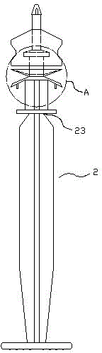
[0028] like Figure 1-8 As shown, a locking structure of a syringe and plunger of a safety syringe with a retractable needle tip, including a syringe 1 and a plunger 2 .

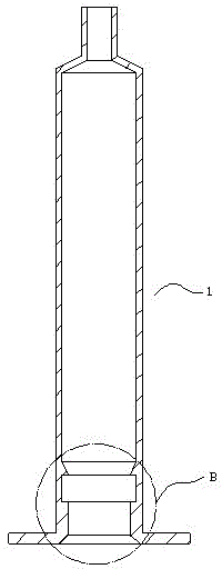
[0029] The inner hole of the syringe 1 is provided with upper and lower convex rings 11 and 12 at the tail. Wherein the upper side 111 of the upper convex ring 11 is an inclined surface arranged obliquely inwardly from top to bottom, and the lower side 112 of the upper convex ring 11 is vertically arranged with the inner hole wall of the syringe. The upper side 121 of the lower protruding ring 12 is arranged perpendicular to the inner hole wall of the syringe, and the lower side 122 of the lower protruding ring 12 is a slope arranged obliquely from top to bottom. An engaging groove 13 is formed between the upper and lower protruding rings 11 , 12 .

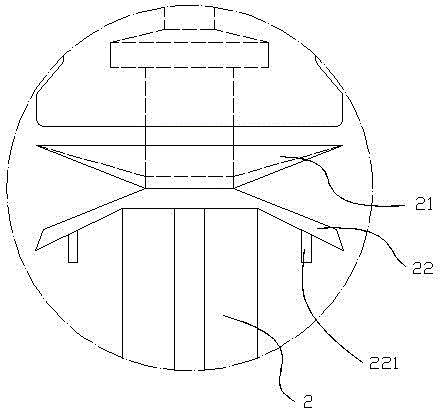
[0030] The body of the core rod 2 is provided with upper and lower flanges 21, 22 whose outer diameter is larger than the inner diameter of the upper and lowe...


PUM


Abstract

The invention discloses a syringe and core rod locking structure of a safety injector with a telescopic tip. The syringe and core rod locking structure comprises a syringe and a core rod. An upper bulge loop and a lower bulge loop are arranged at the tail of an inner hole of the syringe, and a fastening slot is formed between the upper bulge loop and the lower bulge loop. An upper flange and a lower flange which are adjacently oppositely arranged are arranged on the core rod body, the diameter of each of the upper flange and the lower flange is larger than the inner diameter of each of the upper bulge loop and the lower bulge loop while being matched with the hole diameter of the inner hole of the syringe, the upper flange faces towards the head of the core rod, and the lower flange faces towards the tail of the core rod. The upper flange and the lower flange pulled to the tail of the inner hole of the syringe from the core rod can be deformed to overpass the upper bulge loop on the syringe to be locked into the fastening slot.

Description

technical field [0001] The invention relates to a safety syringe with a retractable needle point, in particular to a locking structure of a syringe and a core rod of a safety syringe with a retractable needle point. Background technique [0002] Among the disposable safety syringes, there is a safety self-destruct syringe, the retraction of the needle tip is achieved by manually pulling the core rod back. Here, in order to realize the effective self-destruction of the syringe, avoid excessive force Pulling out from the syringe will cause the needle to be exposed, and at the same time, in order to prevent the needle from piercing the syringe and being exposed after the core rod is pushed back after self-destruction, generally a locking structure is provided between the tail of the inner hole of the syringe and the core rod. [0003] At present, the existing locking structure generally includes an engaging convex ring at the end of the inner hole of the syringe, two engaging f...

Claims


Application Information

Patent Timeline
Patent Type & Authority Patents(China)
IPC IPC(8): A61M5/31A61M5/315
Inventor 陈巧玲
Owner CAINA TECH CO LTD
Why Eureka
Try Eureka