Coating method and coating apparatus
A technology of spraying device and paint, applied in spraying device, spray discharge device, liquid spraying device, etc., can solve problems such as low spraying efficiency
- Summary
- Abstract
- Description
- Claims
- Application Information
AI Technical Summary
Problems solved by technology
Method used
Image
Examples
no. 1 approach
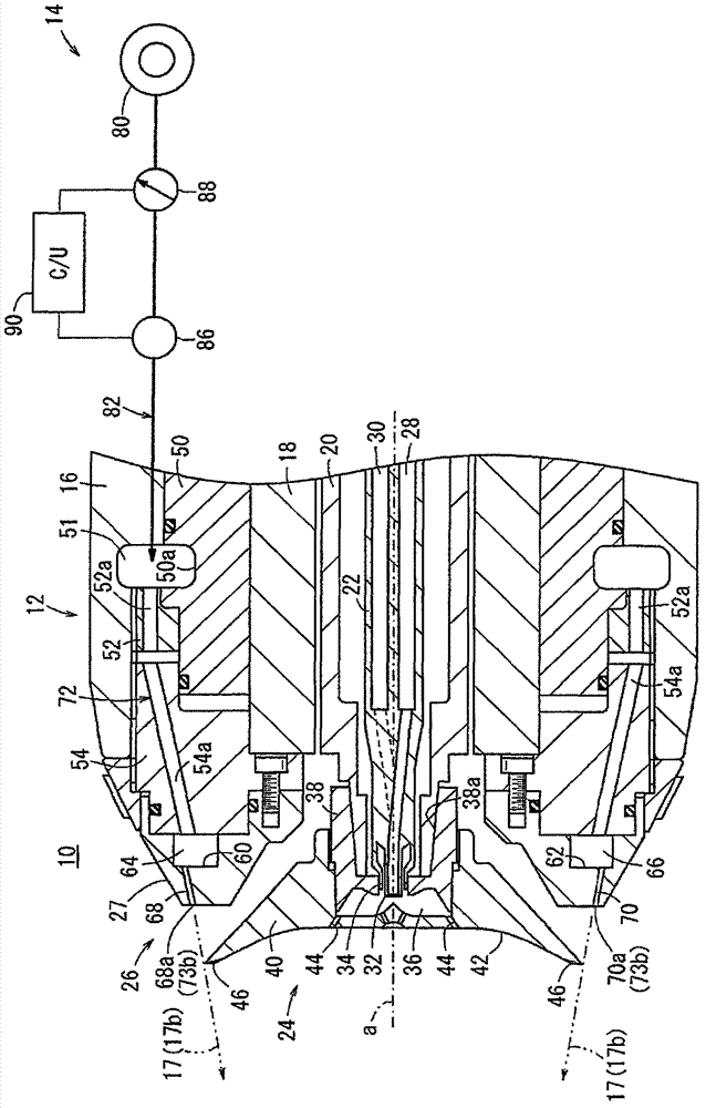
[0028] figure 1 It is a schematic configuration diagram of the coating device 10 of the first embodiment. Such as figure 1 As shown, the coating device 10 has at least a coating gun 12 constituting the main body of the device, and an air supply system 14 for supplying air for molding air 17 to the coating gun 12 .
[0029] The spray gun 12 has: a housing 16 (outer shell); an air motor 18 disposed in the housing 16; a hollow rotating shaft 20 rotated at high speed by the air motor 18; a pipe member 22 inserted in the hollow portion of the rotating shaft 20 ; a bell-shaped rotary atomizing head 24 provided on the front end of the rotary shaft 20 ;
[0030] The air motor 18 is configured to rotate the rotary shaft 20 at a high speed by supplying compressed air from a compressed air source not shown. The rotating shaft 20 is connected to a high voltage generator (not shown) that generates a high voltage. Therefore, a negative high voltage is applied to the rotary atomizing hea...
no. 2 approach
[0074] Figure 7 It is a schematic structural diagram of the spraying apparatus 10a of 2nd Embodiment. Figure 8A is along Figure 7 A cross-sectional view of line VIIIA-VIIIA in (however, illustration of the rotary atomizing head 24 is omitted). In addition, in the spray coating device 10a of the second embodiment, elements that exhibit the same or similar functions and effects as those of the spray coating device 10 of the first embodiment are assigned the same reference numerals, and detailed description thereof will be omitted.
[0075] In the coating gun 130 constituting the main body of the coating device 10 a, a plurality (three in the illustrated example) of annular flow path forming members 132 , 134 , and 136 are arranged between the casing 16 and the air motor 18 . Hereinafter, the flow path forming members 132 , 134 , and 136 are referred to as “first flow path forming member 132 ,” “second flow path forming member 134 ,” and “third flow path forming member 136 ,...
no. 3 approach
[0102] Figure 9 It is a schematic configuration diagram of the coating device 210 of the third embodiment. Such as Figure 9 As shown, the coating device 210 has at least a coating gun 212 constituting the main body of the device, and an air supply system 214 for supplying air for molding air 217 to the coating gun 212 .
[0103] The spray gun 212 has: a housing (housing) 216; an air motor 218 disposed in the housing 216; a hollow rotating shaft 220 rotated at high speed by the air motor 218; a pipe member 222 inserted in the hollow portion of the rotating shaft 220 ; a bell-shaped rotary atomizing head 224 provided on the front end of the rotary shaft 220 ;
[0104] The air motor 218 is configured to rotate the rotating shaft 220 at a high speed by supplying compressed air from a compressed air source (not shown). The rotating shaft 220 is connected to a high voltage generator (not shown) that generates a high voltage. Therefore, a negative high voltage is applied to the...
PUM
 Abstract
Description
Claims
Application Information
 - R&D
- Intellectual Property
- Life Sciences
- Materials
- Tech Scout
- Unparalleled Data Quality
- Higher Quality Content
- 60% Fewer Hallucinations
Browse by: Latest US Patents, China's latest patents, Technical Efficacy Thesaurus, Application Domain, Technology Topic, Popular Technical Reports.
© 2025 PatSnap. All rights reserved.Legal|Privacy policy|Modern Slavery Act Transparency Statement|Sitemap|About US| Contact US: help@patsnap.com


