Method of manufacturing wind energy facility rotor blade section with carbon fibre reinforced main belt

A technology for wind turbines and manufacturing methods, applied in the direction of final product manufacturing, sustainable manufacturing/processing, household appliances, etc., which can solve problems such as complex processes and difficult bonding of main beam covers

Inactive Publication Date: 2013-03-06
NORDEX ENERGY
View PDF3 Cites 3 Cited by
  • Summary
  • Abstract
  • Description
  • Claims
  • Application Information

AI Technical Summary

Problems solved by technology

However, the process is complex and additionally presents difficulties in bonding the main beam caps to the half-shells

Method used


Image

  • Method of manufacturing wind energy facility rotor blade section with carbon fibre reinforced main belt
  • Method of manufacturing wind energy facility rotor blade section with carbon fibre reinforced main belt

Examples


Embodiment Construction

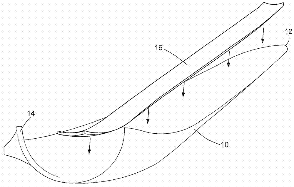
[0057] exist figure 1 In , a half-shell mold 10 can be seen having an end 12 at the tip of the blade and an end 14 at the root of the blade. The cross-section of the end 14 of the half-shell mold 10 at the blade root forms a semicircle. The overall length of the half-shell mold 10 is, for example, 40 m or more, 50 m or more or even 60 m or more. In these wind turbine rotor blades, for reasons of strength and weight, it is often justified to use carbon fiber reinforced main spar caps.

[0058] This figure illustrates how a wind turbine rotor blade part 16 manufactured according to the method of the invention is placed in the half-shell mold 10 . The wind turbine rotor blade part 16 extends approximately over the entire length of the half shell mold 10 , but has a smaller width, measured in the depth direction of the outer contour. Along its leading and trailing edges extending in the longitudinal direction, the wind turbine rotor blade part 16 has a figure 1 Laminar connect...


PUM

PropertyMeasurementUnit
thicknessaaaaaaaaaa

Abstract

The present invention relates to a Method for producing a wind turbine rotor blade part with a carbon fiber-reinforced main spar cap. The method includes: inserting a layer of a first fibrous material into a mold, wherein the fibrous material extends over a first width, inserting a first distribution medium and a plurality of layers of a carbon fiber material into the mold above the first distribution medium, wherein the layers of the carbon fiber material extend over a second width smaller than the first width, so that connecting sections of the first fibrous material protrude beyond the carbon fiber material on both sides thereof, inserting a second distribution medium and arranging an extraction channel above the carbon fiber material, arranging sprue channels in the region of the connecting sections, closing the mold and extracting the air therefrom via the extraction channel and feeding liquid plastics material that hardens through the sprue channels.

Description

technical field [0001] The invention relates to a method of manufacturing a wind turbine rotor blade component with a carbon fiber reinforced main spar cap. Wind turbine rotor blades or parts thereof such as half shells are usually manufactured from fiber reinforced plastic materials. Combinations of fiberglass and polyester or epoxy resins are often used. Background technique [0002] Publication EP0525263A1 discloses a vacuum introduction process for manufacturing fibre-reinforced plastic parts. In this known process, layers of fiber material are inserted into a mould. Below and above these fibrous material layers, respectively, a distribution medium is provided which is separated from those fibrous material layers by a plurality of further layers made of plies known as exfoliated plies. On the bottom side of the mould, injection channels are provided below the lower distribution medium and suction channels are provided above the upper distribution medium. The airtight...

Claims


Application Information

Patent Timeline
Patent Type & Authority Applications(China)
IPC IPC(8): B29C70/34
CPCB29C70/547B29K2707/04B29C70/548B29L2031/085B29C70/443B29C70/549Y02P70/50
Inventor M·弗兰科斯基D·奥斯蒂纳特
Owner NORDEX ENERGY
Why Eureka
Try Eureka