Anti-winding built-in water seal apparatus

A water sealing device and anti-winding technology, which is applied in water supply devices, indoor sanitary plumbing devices, buildings, etc., can solve problems such as easy winding, upward overflow waterway blockage, etc., and achieve low cost, simple structure, anti-winding and anti-blocking Excellent effect

Active Publication Date: 2013-03-06
BEIJING KANGZHIWEI SCI & TECH
View PDF7 Cites 3 Cited by
  • Summary
  • Abstract
  • Description
  • Claims
  • Application Information

AI Technical Summary

Problems solved by technology

However, the outer periphery of the small standpipe is very easy to wrap debris, causing blockage of the upward overflow waterway

Method used


Image

  • Anti-winding built-in water seal apparatus
  • Anti-winding built-in water seal apparatus
  • Anti-winding built-in water seal apparatus

Examples


Embodiment 1

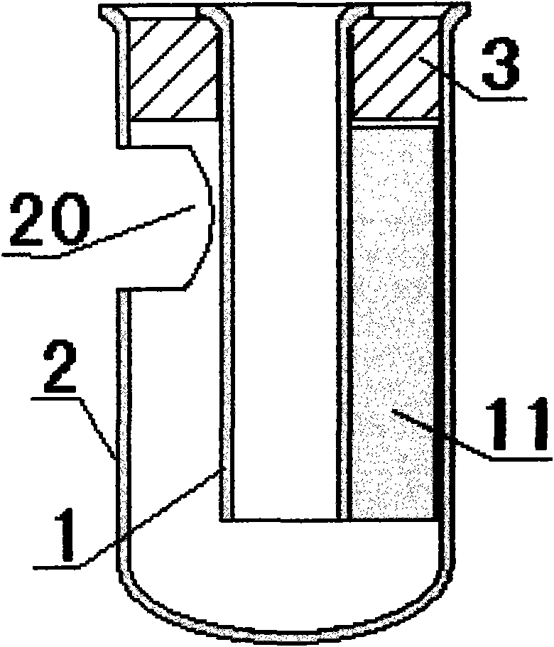
[0023] Embodiment one, such as figure 1 As shown, the anti-winding built-in water seal device of the present invention includes a small water riser 1, the outer circumference of the upper end of the small water riser 1 is fitted with a water storage bucket 2 with a lateral water outlet 20 on one side of the upper part, and a closed bottom. There is sufficient space for flowing water between the lower opening of 1 and the lower bottom surface of water storage bucket 2, and the vertical stop extending to the inner wall of water storage bucket 2 is formed on the opposite side of the small vertical pipe 1 to the side water outlet of water storage bucket 2 Bar 11 (or the other side opposite to the water outlet of the storage bucket side is shaped on the vertical limit bar that stretches out the small standpipe outer wall of the water). The outer periphery of the upper mouth of the small riser pipe 1 is fitted on the upper mouth of the water storage bucket 2 by the gasket 3 (or the ...

Embodiment 2

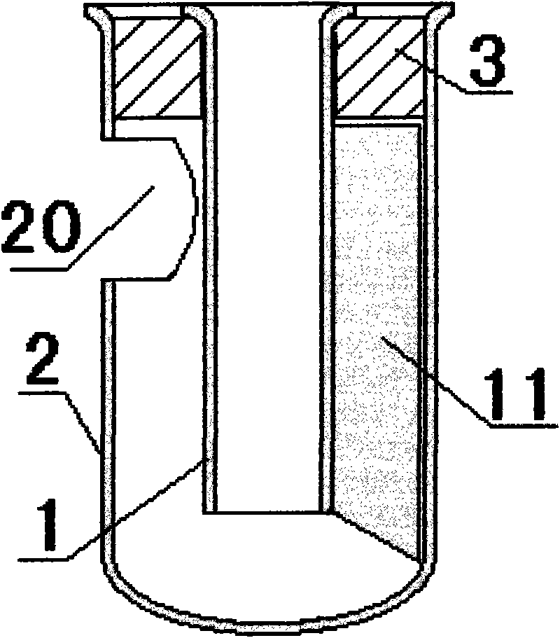
[0024] Embodiment two, such as figure 2 As shown, the difference between the anti-winding built-in water seal device of the present invention and Embodiment 1 is only that the inner side of the lower end of the vertical limiting strip 11 is flush with the lower wall adjacent to the small sewer riser 1, and the vertical limiting The lower end of the bar 11 is inclined downward from the inner side to the outer side.

Embodiment 3

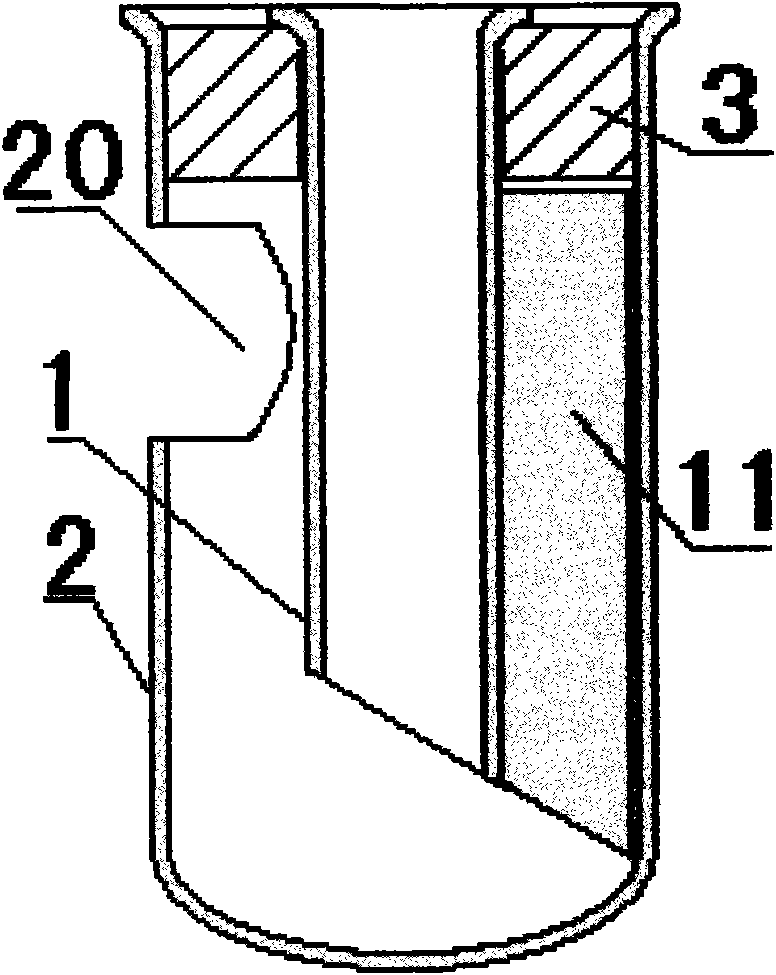
[0025] Embodiment three, such as image 3 As shown, the difference between the anti-winding built-in water seal device of the present invention and the second embodiment is only that the lower opening of the small vertical pipe 1 slopes downward from the water storage bucket 2 side to the water outlet side to the other side.


PUM


Abstract

The invention relates to an anti-winding built-in water seal apparatus used for solving a problem of easy winding and blocking of existing built-in water seals. The apparatus comprises a small draining riser pipe. A water storage tank is sleeved on the periphery of upper end of the small draining riser pipe. A laterally oriented water outlet is provided on one side on the upper part of the water storage tank, and the bottom of the tank is sealed. A vertical stopping strip extending towards the side opposite to the laterally oriented water outlet is provided on the small draining riser pipe, or a vertical stopping strip extending towards the outer wall of the small draining riser pipe is provided on the water storage tank on the side opposite to the laterally oriented water outlet. The small draining riser pipe is inclined downwards from the side of the laterally oriented water outlet of the water storage tank to the other side. A sector plug is provided on the lower end of the vertical stopping strip inclined from the inner side to the outer side. The inner side of the sector plug is connected to the outer wall of the lower port of the small draining riser pipe, and transversally reaches the inner wall of the water storage tank. Or the inner side of the sector plug is connected to the outer end of the water storage tank, and transversally reaches the outer wall of the lower port of the small draining riser pipe. The lower part of the vertical stopping strip is inclined downwards from the inner side to the outer side. The apparatus provided by the invention has the advantages of simple structure, low cost, and excellent anti-winding and anti-blocking effects.

Description

technical field [0001] The invention relates to a water sealing device, in particular to an anti-winding built-in water sealing device. Background technique [0002] Existing built-in water seal comprises a small water riser, and the outer periphery of the upper end of the small water riser is fitted with a water storage bucket with a sideways water outlet bottom closed on one side of the upper part. There is plenty of room for running water. However, the outer periphery of the small standpipe is very easy to be wound with sundries, causing blockage of the upward overflow waterway. Contents of the invention [0003] The purpose of the present invention is to overcome the above-mentioned defects of the prior art and provide an anti-winding built-in water seal device. [0004] In order to achieve the above object, the anti-winding built-in water seal device of the present invention includes a small vertical pipe for sewer, and the outer circumference of the upper end of th...

Claims


Application Information

Patent Timeline
Patent Type & Authority Applications(China)
IPC IPC(8): E03C1/284
Inventor 魏富儒
Owner BEIJING KANGZHIWEI SCI & TECH
Why Eureka
Try Eureka